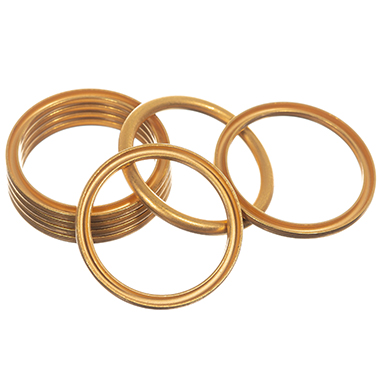
Need an O-ring for your application?
Use our interactive O-ring calculator to help select the optimum size O-ring to use, in accordance with the principles within ISO 3601. With a user friendly interface, and no login required, it will give recommended housing dimensions and allow you to assess the impact on sealing parameters where hardware sizes are adjusted to suit your specific application.
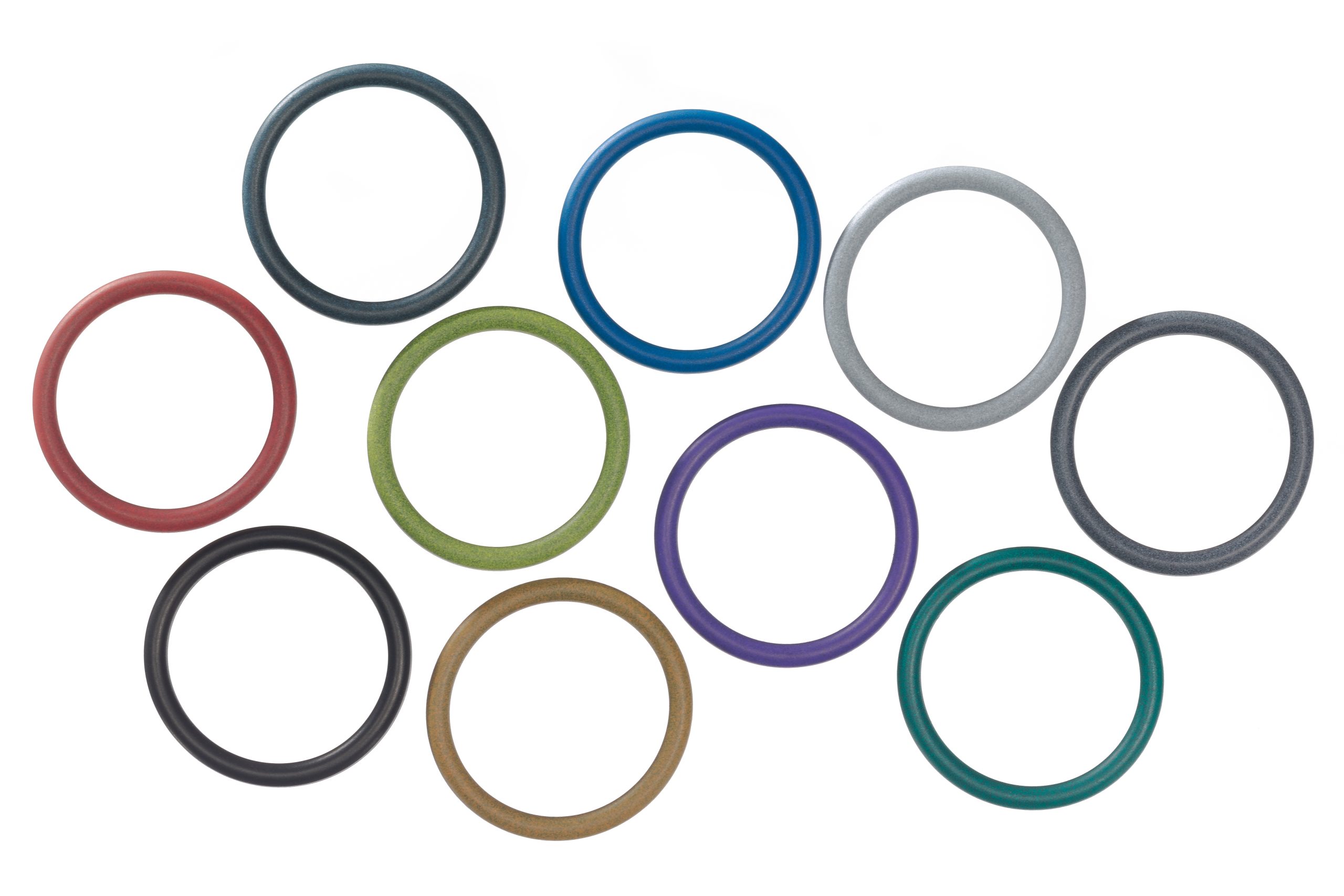

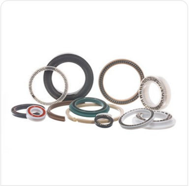
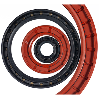
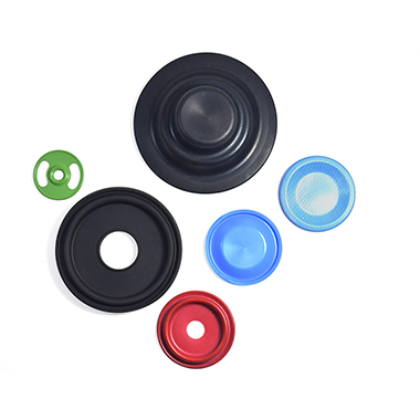
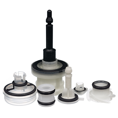
Product Range
Our seal products range from simple static O-rings to complex and bespoke seal designs in specialist materials. Whatever your application, we have the seal product for you.