Seals for renewable energy applications
Renewable energy is derived from our planet’s natural resources such as sunlight, wind, rain, tides, waves, biomass and thermal energy stored in the earth’s crust. With increasing fossil fuel prices, and the very real threat of global warming and climate change to our planet; the development of renewable energy production sources is more important than ever
In this article, we take a deeper look into seals for renewable energy applications and the different types of power the natural world provides.

Geothermal energy and hydro power
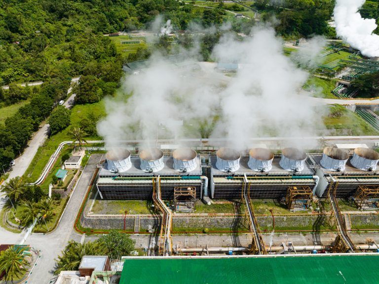
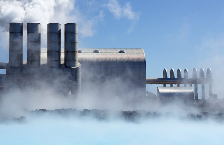
Geothermal energy is generated from heat from the sub-surface of the earth. Heat is produced by the decay of elements known as radioactive isotopes. This is a constant process in the earth’s core, and as a result temperatures reach in excess of 5,000˚C. Wells of up to a mile deep or more are drilled into underground reservoirs to tap into the geothermal resources. Steam from these reservoirs is harnessed and used to rotate turbines that activate a generator, which in turn produce electricity.
There are different designs of geothermal power plants. A dry stream plant extracts steam directly from the ground and into a turbine, which drives a generator to produce electricity.
The most common type are flash plants; where high pressure hot water is pumped to the surface and mixed with cooler, lower pressure water. This causes the fluid to rapidly vaporise, and the resulting steam drives a turbine.
Binary power generation plants differ from the other systems. The water and steam from the geothermal reservoir never come in contact with the turbine units. A low-moderately heated geothermal fluid, and a secondary “binary” fluid (with a much lower boiling point than water) pass through a heat exchanger. The heat from the geothermal fluid causes the secondary fluid to flash to vapour. This drives the turbines to power the generator.
Sealing in Geothermal applications

Application conditions to consider are high temperature requirements (up to 320°C) and high pressure requirements (up to 1400 BAR).
Steam is present in working turbines and drilling fluids present downhole (which may sharply change in viscosity during operational stages). Sealing drilling bores with large radial gaps is necessary.
Seals are required in a range of materials to suit application needs; EPDM with steam, FKM/FFKM for high temperatures. Additionally, NBR has high expansion capabilities to seal large radial gaps.
Spring energised seals offer exceptional pressure and temperature compatibility – offered in NACE approved springs (corrosion resistant). Packer elements can also assist bore alignment and offer a dense sealing arrangement which prevents cross contamination of fluids.
Hydro power
All forms of hydropower convert energy from water flow into electricity through the operation of a turbine and generator. There are different methods of hydropower production. Three of the main techniques are Impoundment, Diversion and Pumped Storage. Impoundment uses a dam to store river water in high reservoir. Water in the reservoir is manually released and the kinetic energy of its flow (as a result of gravity) is converted to electricity through a turbine and a generator. A diversion facility channels a portion of a flowing river through a separate channel. The channel will direct the water to a turbine and turn it before it re-enters the river at a lower point.
The principle behind a pumped storage facility is that water is pumped to a higher elevation, and then manually released back to the original lower reservoir. The energy used to originally pump the water up can be extracted by a turbine and generator for use as electricity. The idea of pumped storage is to store the energy like a battery and use this in times of demand.
Sealing in hydro power applications
This technology provides a range of application environments, with varying water conditions and sources.
Hydro power stations contain large and heavy-duty mechanisms when dictating the flow of water. High rotational speeds will be achieved on some turbines. Wear and abrasion resistance must be considered with potential for higher load impacts from initial water release. Seals in a comprehensive range of elastomer compounds must be considered to ensure compatibility between varying water conditions.
Heavy duty application rotary seal designs are suitable (in some cases with metal casings. Additionally, PTFE seals are suitable for applications that require abrasion and wear resistance.

Wind energy
This is the process of converting the kinetic energy of wind into electricity through a wind turbine.
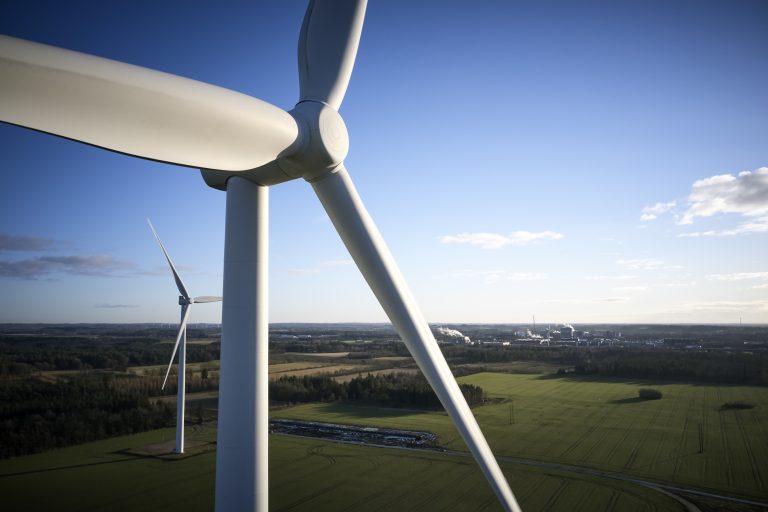
Most wind turbines feature three blades, and the shape of the blades are similar to the design of an aircraft wing so that the air flow around them provides lift. The force of the lift is much stronger than the wind’s force against the front side of the blade (which is called drag). The combination of lift and drag causes the rotor to spin like a propeller which in turn causes rotation of a shaft at the blades’ axis. The shaft is attached to a generator, which produces electricity from the torque of the shaft.
A streamlined enclosure called the nacelle houses the key components of the turbine; including the gears, rotors, braking system and generator. There is a pitch control mechanism (comprising of hydraulic cylinders) to ensure that the blades are rotated at an angle to receive the wind and encourage lift most efficiently, and a yaw mechanism (located at the base of the nacelle) which rotates the entire body so that the front of the hub faces the direction of the wind.
The shaft is incorporated into a gear system which has another higher speed shaft attached to the end. The gear box provides a gear ratio that can be up to 100:1, relative to the low-speed shaft connected to the blades. The high-speed shaft provides torque to a generator which converts this force into electricity.
Application conditions
Application conditions for seals can vary depending where in the turbine they are located. General environmental factors include varying weather conditions, vibration, contaminants, corrosion, altitude and diverse (and often fluctuating) temperature ranges (-40˚C to 85 ˚C). Often long life cycle and ease of installation are considered important (as downtime and maintenance are extremely costly).
Areas of application are broken down below.
Gearboxes, braking systems and Pitch & Yaw systems
Gearboxes:
There are a range of rotational shaft speeds to consider here. Typical high-speed shafts can reach approximately 2,000 RPM so require high wear resistant seals and shaft misalignment often needs to be considered. In low-speed shaft applications, contamination from outside elements must be prevented. Rotary V-Seals reduce contact pressure as RPM increases (due to centrifugal force) which allows operation at a variety of speeds and reduces the chance of heat friction/friction loss. They also offer flexible lip arrangement to compensate for shaft misalignment. Oils and grease are used to lubricate systems so multiple compounds are available for compatibility.
Braking systems:
A wide range of pressure requirements are seen; low working pressure until brakes are applied, and then high and uni-directional pressures activated. A range of brake fluids and oils are used so material compatibility must be considered. O-ring energised Polypak® seals, step seals and slipper seals all seal at a flexible tolerance range – offering sealing capability at low and higher pressures. PTFE seals offer a very consistent and strong chemical resistance. Scraper seals contain fluids in brake system compartments and prevent components running dry.

Pitch & Yaw systems
These present both static and dynamic sealing applications, but inconsistent dynamic operation (as it depends upon wind conditions). Both low and high pressure will be seen (for example, accumulators within pitching system present up to 250 BAR). Shaft offset/misalignment must be considered in heavy duty yaw systems.
Hydraulic fluids and diverse lubricants require material compatibility choices. O-ring energised PTFE step seals will seal at a flexible tolerance range and offer sealing capability at low pressures. Engineers can design sealing assemblies, made of other products, to work together to seal against high pressures. Polypak® seals also offer sealing when high pressure is applied and when under ambient conditions. O-ring energisers and wear rings help to contain shaft run out.
Seals for Renewable Energy Applications
In summary, seals are a vital part of the critical function of components in renewable energy power generation. They are required to provide long term functionality and provide durability in harsh environmental conditions. Our range of engineered sealing materials are designed to withstand critical sealing characteristics in these applications, including wear resistance, high pressure and high temperature conditions.
Hydrogen and renewable energy is one of our key industries. Read more HERE