What is hardware surface finish?
Any surface can look (and even feel) perfectly smooth. However, look closely enough with high magnification and all surfaces will have a degree of fluctuation. The topography will look similar to a mountain range or the surface of the moon!
The way a surface is produced or machined, along with any subsequent processes such as coating or plating, often determines its roughness.
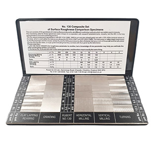
Just a couple of decades ago, the standard approach to assessing surface finish was to use comparison plates. These small specimen sections were made by turning, grinding, or milling the material. Inspectors would then run a fingernail across the finished part and the plates to determine which one matched most closely.
What is Ra?
Historically, seal catalogues typically recommended a surface finish using just the Ra (metric) or CLA (Centre Line Average, inches) parameter. Little regard was given to what the seal was being expected to do.
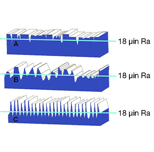
Ra simply, is the mean roughness. The average calculated from the peak heights and valley depths. A surface that is mostly spiked can have the same Ra value as one that is mostly troughed. However, each could have a very different impact on seal performance. Today, surface finish measuring equipment is more sophisticated. It’s capable of tracing a surface finish using a diamond tipped stylus, or non-contact 3D laser scanning.
These devices are now reasonably affordable and provide a sophisticated level of results from essentially a portable machine. Consequently, these instruments can now analyse the surface roughness profile, trace, also calculate a large range of parameters that define that profile. This includes Ra, Rt, Rz, Rmax, Rmr (bearing ratio) and even skewness parameters. What these are, and how they should be measured, have generally been well captured in standards. These standards include ASME B46.1, ISO 4287, ISO 4288 and the upcoming ISO 21920.
Why is surface finish important for sealing systems?
To ensure seal effectiveness, a common assumption for specifying a hardware surface finish is the smoother the finish the better. However, this is not always the case. If the seal application is static and is sealing a low molecular size gas such as helium; then a very smooth surface would be preferable.
This is often referred to as a “closed” surface (with no peaks and very few, shallow valleys). The seal mates tightly against the hardware, ensuring the leak path for the gas is reduced as much as possible. Even in this scenario, the required surface roughness can be influenced by other factors. These include the hardness (or rather, softness) of the seal material and the pressure being applied, both by the initial seal squeeze and the applied gas pressure.
It’s important the interface between the seal and the hardware is well lubricated. This is critical for some dynamic applications for either seal friction (and hence noise, vibration and heat) or wear life.
This is partly achieved by ensuring that the surface is more “open”, with small valleys or troughs to trap the lubricant -but no sharp peaks that would abrade the seal material. In these application cases, if the dynamic hardware surface (rod, shaft or piston bore) is too smooth, then the seal can wear prematurely. This can cause juddering, squeal and excessive heat build-up.
Tribological performance consideration
As a result, for dynamic applications it is important to consider all the factors affecting the tribological performance. These include the seal (design, material), the dynamic hardware (hardness, material type) and the fluid (viscosity, lubricity, contamination). The hardness of the dynamic hardware can also be a significant factor. Hardened or chromed steels around the 50 Rockwell C level or less can often be polished by the seal itself. Therefore, even if the initial roughness is sub-optimal, good sealing performance is achieved after a brief period of bedding in.
With the use of high hardness coatings such as HVOF and DLCs, the much softer seal material is very likely to be abraded by the hardware. In these cases, it’s essential to ensure that the optimal surface finish is met. This often requires a finer finish prior to the coating process. This is because coatings can be rougher than the substrate material, and post-process polishing is challenging with such hard coatings.
Any other factors to consider?
Yes! Another thing to consider is the direction (or lay) of a particular surface finish. Machining marks, scratches, dents or other hardware damage that cut across a sealing contact face are likely to result in leakage. This is compared to (for example) concentric machining marks in the base of an axial face-seal O-ring groove. It is important to consider specifying a lay direction when applying surface finish requirements to the hardware design specifications and drawings.
What hardware surface finish should you specify?
Despite complexities involved in hardware surface topography, the sealing industry has developed a comprehensive set of recommendations. These can vary a little between different manufacturers and suppliers. Given the specificity of the seal design and material, they’re best found within the specific literature for the products considered for the application.
This is a good starting point, but for each individual application it’s worth considering whether these specifications should be addressed. For example, specifications could be tightened, or perhaps even loosened to ensure that performance targets can be met. This would reduce the need to over-specify the surface finish – because this can add unnecessary processing cost to a part.
The practicalities involved in accessing the surface to measure also need consideration. It’s notoriously difficult to check the sidewalls of an O-ring groove, especially in a rod/ID sealing configuration. Cylinder bores are often less tightly defined due to stylus/probe access issues compared to rods and shafts.
Importantly, anyone producing and checking a particular surface finish must have both the equipment and the understanding to do so. This is very important if using relatively modern and less well known parameters such as Rmr (or Tp, bearing ratio).
Further detail can also be found in the ISO and ASME standards regarding measuring settings. For example, filtering/cut-off values, stylus tip radius, measuring, evaluation and tracing lengths. When validating a supplier’s measurements, it’s important these machine settings are identical. Failure to do so will result in differing surface finish values obtained on the same part. Those standards are not specific to sealing applications. Generally, we’d recommend a cut-off filter (λc) of 0.8, unless measuring very fine (< 0.1 µm Ra) surface finishes where 0.25 would be more suitable, with a 2 micron stylus tip in all cases.
Engineering expertise
Specifying the right surface finish for the hardware components that contact a seal can be complex and daunting. We will ensure an optimum finish and right-first-time seal performance. This is with our core understanding, and consideration of relevant parameters for the given application.
For more on our engineering expertise, read HERE