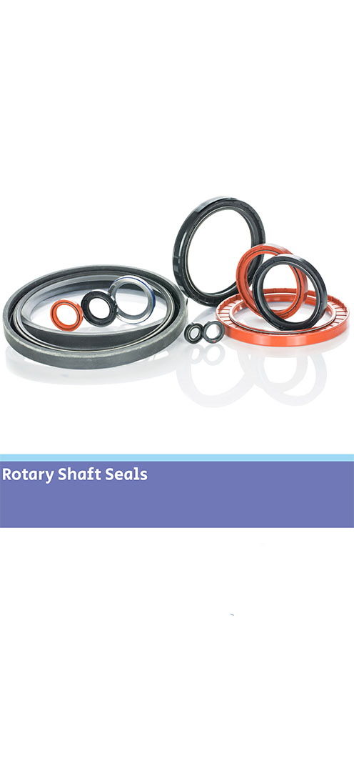
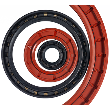
Precision Sealing for Naval Radar Slip RingPrecision Sealing for Naval Radar Slip Ring The application Our customer is a globally recognised leader in the design and manufacture of advanced slip ring systems and contactless rotary joints. Their technology ensures the reliable transmission of power, data, and media across a wide range of rotating interfaces. Read more about how our engineers developed a custom spring-energised seal for this application. The application for this project is as demanding as they come. A naval radar system operating in some of the harshest conditions on the planet.Mounted on a naval vessel, the slip ring assembly must operate continuously. Therefore it needs to function flawlessly, protecting electrical components whilst exposed to the elements (seawater, rain and wide temperature fluctuations). The challenges As well as these demanding conditions, the application itself also had several challenges. Furthermore, the design is a compact seal envelope, meaning design and installation need careful consideration.A durable seal is needed - the expectation is that it can withstand over 6 million cycles across a 10-year service life. The seal required minimal breakout friction to avoid wear and conserve energy consumption.This application required a rotary seal with low temperature capability and excellent resistance to oil-based fuels. The new design will replace the existing seal in the available housing between the rotating metal faces. We concluded a standard spring energised rotary seal would not work in the application, therefore we created a bespoke design. Our sealing solution Our engineers developed a custom spring-energised seal, tailored precisely to the application’s needs. We adapted the Parker Praedifa NLO profile and optimised it with a low-load spring for reduced friction, and a high-performance material formulation offering exceptional wear resistance.Additionally, we included a design feature - heel slots allowing for dowel pin integration within the hardware to provide enhanced application stability. Results The final design delivered excellent sealing performance, passed all endurance tests, and met the full 10-year lifecycle requirement. Consequently, it maintained low friction throughout, ensuring energy efficiency and minimal wear. This is exactly what’s needed for a radar system where reliability is non-negotiable.Learn more about our rotary seals HERE.

Precision Sealing for Naval Radar Slip Ring 
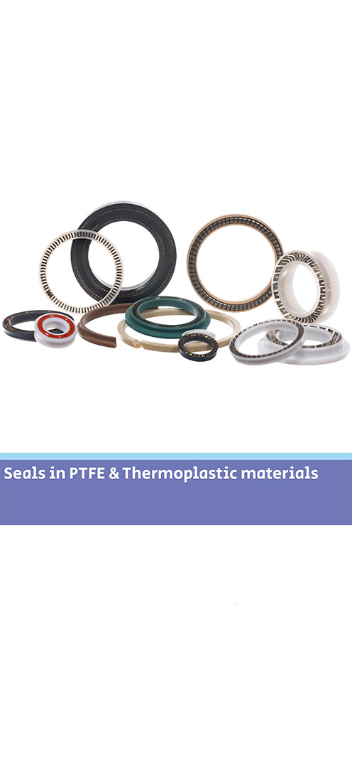
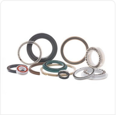
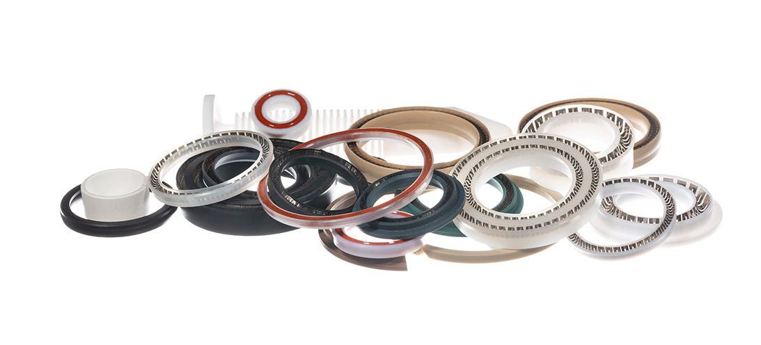
Why use PTFE seals?Why use PTFE seals? Polytetrafluoroethylene (PTFE) is a thermoplastic polymer. PTFE seals can be used in a variety of sealing applications. It’s suitable when application conditions exceed parameters of elastomeric seal use but not to the extent of a metal seal. What is PTFE? It has a high melting point (342 °C) and morphological characteristics. These allow seal components made from virgin PTFE to be used continuously at service temperatures of up to 260 °C. With the addition of fillers – up to 300°C. It has the unique ability to resist material degradation, heat-aging and alteration in its physical properties during temperature cycling. Alongside this rare combination of material characteristics, PTFE also has unlimited shelf life. Why use PTFE seals? Notably PTFE demonstrates extraordinary chemical resistance. The intrapolymer chain bond strengths preclude reactions with most chemicals, thereby making it chemically inert at elevated temperatures and pressures with virtually all industrial chemicals and solvents. Only a few media (some molten alkalis) are known to react with PTFE seals making them the perfect sealing solution for highly aggressive chemical applications.PTFE also has the lowest friction coefficient of any known solid. It has self-lubricating capabilities which offers continuous dry running ability in dynamic sealing applications and has superb stick/slip capabilities. Focus on dry coatings The advantages of using PTFE in sealing applications are multiple:Functionality at high and low temperaturesDynamic sealing with high wear capabilitiesHigh pressure sealing (using combinations of PEEK back-up rings)Compatibility with highly aggressive chemical combinations.Our range of PTFE seal products include back-up rings, rod and piston seals, slipper seals and spring energised seals in a wide variety of sizes. Materials depend on application requirements. However, we offer a wide range from Virgin PTFE or including filler combinations of MoS2, glass, carbon, carbon fibre, graphite, and bronze.These characteristics make PTFE seals perfect for the demanding applications involved in Oil & Gas, Aerospace, Automotive and Chemical Process markets (to name but a few). Ceetak’s engineering team are experienced in the design of PTFE sealing solutions to meet the complex specifications these types of application demand.Read our overview and more detail about PTFE seals HERE
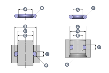
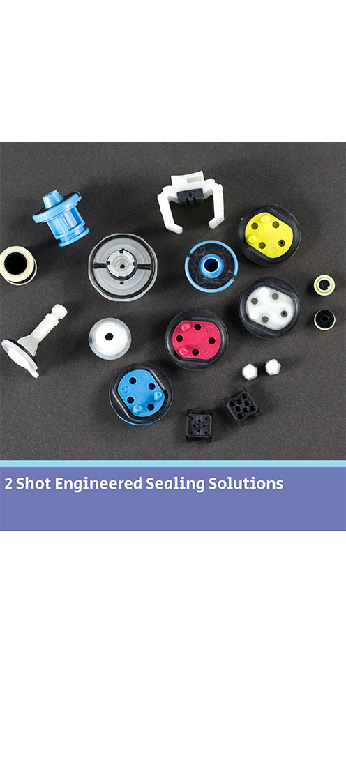
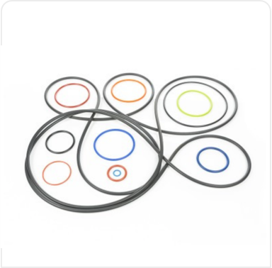
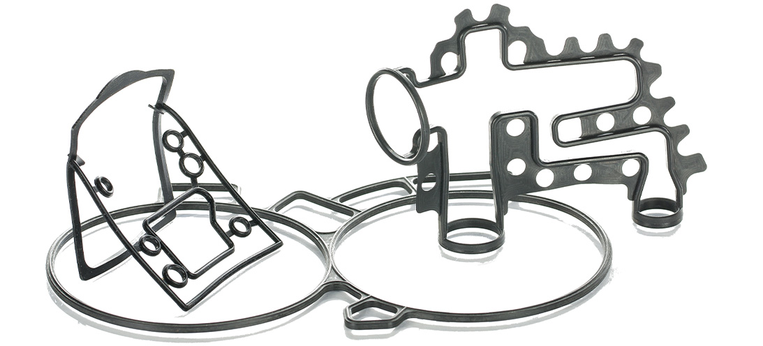
Why use PTFE seals? Why use Push-in-Place gaskets?Why use Push-in-Place gaskets? Where a seal groove follows an irregular path or profile, a common sealing solution is to design a custom Push-In-Place (PIP) gasket. This will have the same profile as the centre line of the groove, and simply drops into place, retained by the features of its own design. Gasket sealing overview There are many ways to seal the static join between two components. This could be to keep fluids inside a cavity, or to keep fluids or contaminants out of a device or assembly. The options will vary from simple O-rings, moulded elastomer gaskets and flat sheet style materials, to liquid gaskets (or RTV’s).As with all sealing applications, the optimal sealing solution is designed by first reviewing the application conditions. These include temperature, pressure, fluid exposure etc. Other variables such as life requirement, equipment serviceability and seal compression set will all be considered. Arguably though, compared to other sealing applications there are considerations when designing face, cover or flange sealing solutions. It is imperative to consider the packaging requirements and assembly issues of gasket sealing options. For example, if there is a need to avoid or seal around bolt holes (or other retaining/clamping devices). Additionally, consideration around optimizing hardware wall sections or depths can play an important part in choosing the most suitable gasket sealing technique. What are Push-in-Place gaskets? With the right combination of application conditions, an O-ring style approach to sealing may be the most appropriate. O-rings tend to require relatively shallow grooves compared to their cross section in one half of the assembly. In cases where the groove is round in plan view – they can be a good solution.However, in cases where the groove follows a more irregular path or profile (frequently referred to as a “racetrack”) the O-ring can sometimes pop out in places. This will be often where the two housing parts are being brought together. A common solution is designing a custom moulding with the same profile as the centre line of the racetrack groove. This will simply drop into place.A similar approach is used when the application or hardware constraints steer the design towards a gasket that has a greater cross section depth compared to the width. This would typically be designed so the centre line of the gasket matches the centre line of the groove plan profile – again so that it drops easily into place.An inherent problem with gaskets that can drop into place is that often, they easily drop out of place too. This can occur when the component needs to be inverted or has the potential for rough handling during assembly. Consequently, the gasket may become partially or fully dislodged from the groove, which results in a badly sealed interface. The best solution to this issue is to incorporate retention pips or bumps in the gasket design. This is a solution known as Push-In-Place (PIP) gaskets. These require a distinct force to put them into the groove. Subsequently, they require more than just gravity to get them out of the groove. Why use Push-in-Place gaskets? There are other less effective solutions for tricky groove sealing, such as the use of a sticky grease, or the use of an adhesive. These can bring compatibility and health and safety issues to consider. Additionally, the risk that any contaminant could keep the gasket off the surface that it’s supposed to be sealing against. As a result, the integrity of the seal can be severely compromised.Neither of these approaches can be recommended. Instead, the use of retention pips is a safe and secure way of ensuring the gasket remains in the groove. How do retention pips work on a gasket? To determine the optimum number, size and position of the retention bumps, Finite Element Analysis is used. This ensures they provide sufficient squeeze to prevent the gasket being easily dislodged. Additionally, it’s important the groove space isn’t overfilled with seal material or interfering with the seal compression footprint against the hardware faces.The bumps can be strategically positioned to control any distortion of the gasket under pressure or temperature conditions. For example, low temperature conditions can shrink the gasket and tighten the radius it adopts around a bend in the racetrack profile. This can reduce the seal compression locally and potentially create a leak path.By positioning retention bumps at either end of the bend, the thermal contraction will be controlled to minimize leakage risk.Effective retention is needed to ensure the gasket remains correctly located in the groove even with varied use. For example, if the part needs to be inverted (sometimes the preferred assembly method for practical reasons). Alternatively, it could be subject to rough handling.For large gaskets this is normally the most effective solution. On smaller gaskets (particularly those located well inside the periphery of the assembly), there is a significant risk of a dislodged gasket being totally undetected unless using a PIP gasket design. Monitoring gaskets - human eye or testing machinery It is possible to include tell-tale signs on a gasket design. For example, if a part of the elastomer gasket protrudes sideways through a gap in the housing wall the presence of the gasket can be checked. This will be either with the human eye or an automated vision system. However, this does not ensure correct seating all around the gasket length. Additionally, it cannot be used for internal gasket locations. In these cases a missing or badly fitted gasket would only be discovered during post-build testing, or even worse with a machine failure at a customer.If included at the design stage, the small additional tooling and material costs associated with a PIP gasket are negligible compared to the costs of an impossible assembly scenario, strip and re-build costs on the assembly line, or the consequential costs associated with failure of an assembly once delivered to a customer.More information on PIPs and gaskets can be found HERE
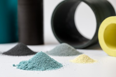
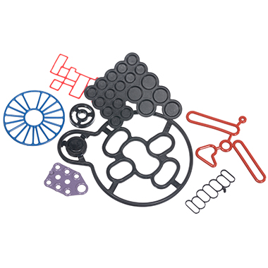
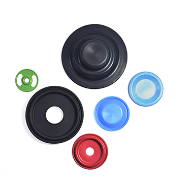
Why use Push-in-Place gaskets? 3D printing for seals3D printing for seals 3D printing has developed significantly and now performs a crucial role in many applications. 3D printed products vary from fully functional to purely aesthetic applications – commonly for manufacturing. Here we discuss how our engineers use this technology to demonstrate a seal concept. What is 3D printing? The typically common name for additive manufacturing is 3D printing. The process involves the construction of a three-dimensional shape designed and generated from a computer aided design program (or CAD). The most typical process used for 3D printing is FFF (Fused Filament Fabrication) or FDM (Fused Deposition Modelling).The FDM process uses a continuous filament of a thermoplastic material. It’s then deposited onto the 3D print bed, creating layer by layer, gradually building up the 3D model structure. We commonly use this process to create our design and development range of 3D printed models and seal prototypes. What material is suitable for 3D printing? Material compatibility with the process is imperative and a range of thermoplastic grades are used. Typical suitable material grades include; Polylactic acid (PLA), Acrylonitrile Butadiene Styrene (ABS), Thermoplastic Polyurethane (TPU), Nylon and Polypropylene (PP).The most common grade we use for 3D printing is PLA – for its great strength and stability. We’ve also adapted our design process to use more TPU based material grades, as it loosely demonstrates the same properties as elastomer grades and is better for using in prototype programmes where mechanical fit in groove is tested. Why use 3D printing for seals? 3D printing is used for a variety of designs and seal types. From O-rings, gaskets and lip seals – to grommets, multi shot mouldings and large seal assemblies.Using 3D printing during the initial design stages of a project comes with many benefits. The rapid turnaround means a simple seal design will be produced in around 15 minutes. Additionally, even more complicated parts can be manufactured in the same day. We can even print the application housings – a perfect demonstration to an engineer what they can expect from a seal part. They will see the shape and fit for hardware without the lead time and cost of cutting a prototype tool for moulded parts.This solution is particularly suitable for quick turnaround gasket designs. For example for automotive applications or similar critical markets. Our engineers can design the concept and then 3D print a rapid prototype of a gasket to suit a 3D printed gauge groove. Demonstrating to our customers that the seal has been fit checked for installation, builds further confidence in the design recommendation. Our engineers combine the 3D print with FEA simulation reports to offer a fully engineered sealing solution.Learn more about our design and simulation service HERE
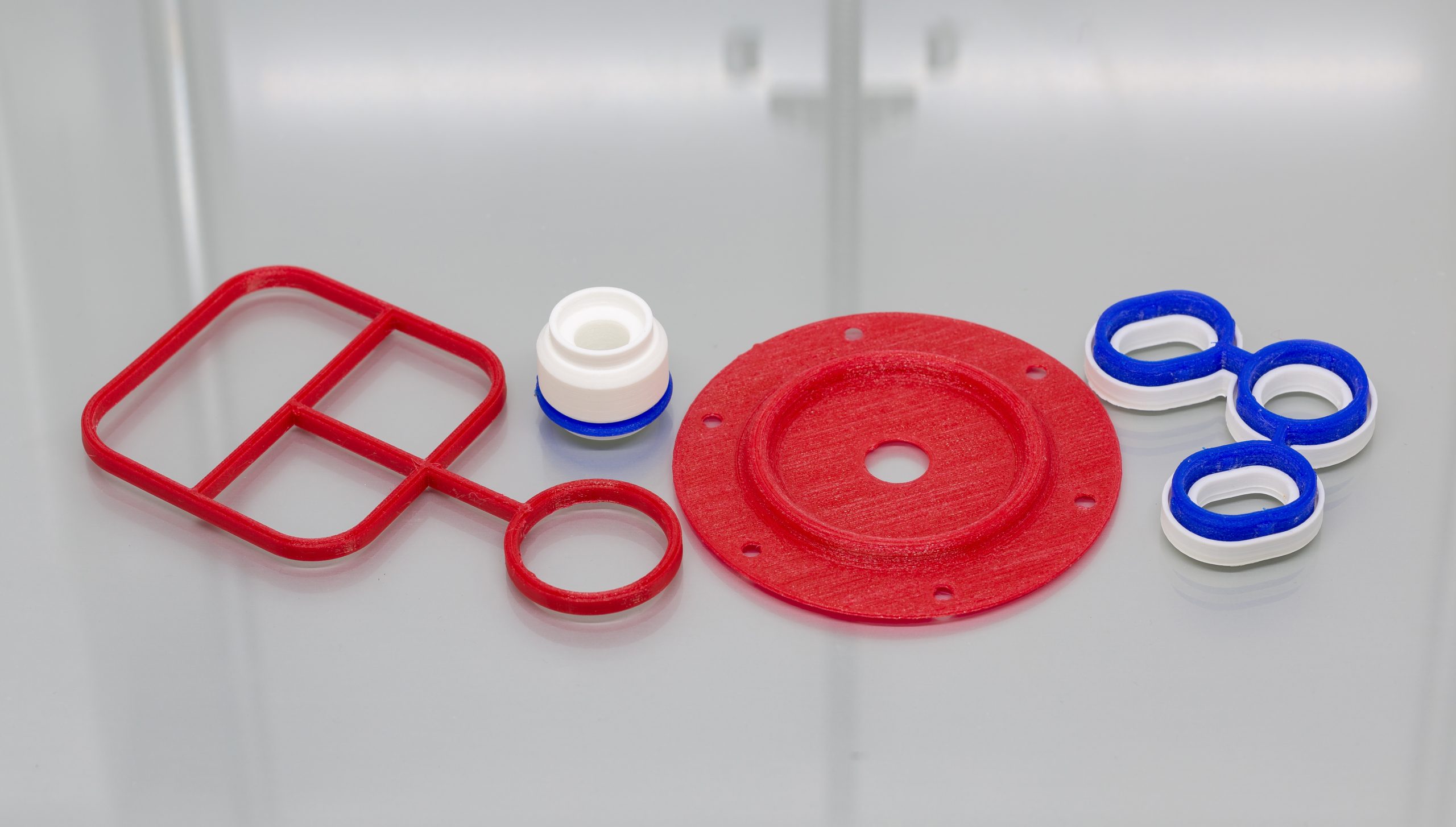
3D printing for seals