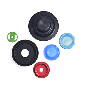
Using Finite Element Analysis (FEA) in seal designUsing Finite Element Analysis (FEA) in seal design Finite Element Analysis (FEA) is a computerised modelling method for predicting how an object reacts to forces, whether directly applied or generated by pressure, temperature effects or vibration. FEA provides data to help predict how a product will function under those applied conditions. Additionally, it identifies areas where the design can be optimised and improved, without having to test multiple prototypes.Our specialist software uses mathematical models to understand and quantify the effects of real-world conditions on a part or assembly. It can be used to identify potential causes where sub-optimal sealing performance has been witnessed and can also be used to guide the design of surrounding parts. Importantly for products such as diaphragms and boots where contact with adjacent parts may need to be avoided. The software also allows force data to be extracted . For example, compressive forces for static seals and friction forces for dynamic seals can be accurately predicted to help our customers in the final design of their products. Why do we use Finite Element Analysis (FEA)? Our engineers encounter many sealing applications that are critical and have many complicating influences. Envelope size, housing limitations, shaft speeds, pressure/temperature ratings and chemical media are all application parameters that our engineers must consider when designing a seal.In isolation, the impact of these application parameters is reasonably straightforward to predict when designing a sealing solution. However, when you compound a number of these factors (whilst often pushing some of them to their upper limit when sealing) it is crucial to predict what will happen in real application conditions. Using FEA as an iterative tool, our engineers can confidently design and then manufacture robust, reliable and cost-effective engineered sealing solutions for our customers.Starting with a 2D or 3D model of the initial design concept, produced within our advanced CAD system, we then apply the boundary conditions and constraints supplied by the customer, including pressure, force, temperatures, and any applied displacements. A suitable finite element mesh is overlaid onto the seal design, ensuring that areas of most interest have the necessary mesh size to ensure accurate results are returned for these regions whilst utilising larger mesh sizes in areas with less relevance or lower levels of displacement to minimise the computing time required to solve the model.Material properties are then assigned to the seal and hardware components. Most sealing materials are non-linear, whereby the amount they deflect under an increase in force varies depending on how large that force is, unlike the straight-line relationship for most metals and rigid plastics, at least over the displacement range relevant to sealing applications. This complicates the material model, and extends the processing time, but we use in-house tensile test facilities to accurately produce the stress-strain material models for our compounds to ensure the analysis is as representative of real-world performance as possible. What happens with the FEA data? The analysis itself can take minutes or even hours of computing time, depending on the complexity of the part and the range of operating conditions being modelled; behind the scenes in the software, many hundreds of thousands of differential equations are being solved.The results are then analysed by our experienced seal designers to identify areas where the design can be optimised to match the specific requirements of the application; such requirements may be for sealing at very low temperatures, a need to minimise friction levels with a dynamic seal, withstand very large pressures without extruding, or whatever sealing system properties are most important to the customer and the application.Results for the finalised proposal can be presented to the customer as force/temperature/stress/time plots, numerical data or animations showing how a seal behaves throughout the analysis, as appropriate to their needs, and can be used as validation data in their system design process. Project 1 case study Faced with very tight packaging constraints, a customer requested a diaphragm component from us for a valve application. Using FEA, we were able to optimise the design not only of the elastomer diaphragm itself, but also propose modifications to the customers hardware components that interfaced with it in order to increase the available space for the diaphragm, keeping material stress levels low to remove any possibility of fatigue failure of the diaphragm over the life of the valve. Project 2 case study A customer approached us to design a PTFE rotary lip seal that had to meet tight maximum torque requirements as their system was driven by a size-limited low power motor with modest levels of torque available.At the same time, high seal tightness was required as leakage of the media would have caused significant problems.By using an iterative FEA process, we produced a seal design that optimised the sealing lip geometries to provide the lowest levels of rotational friction drag whilst ensuring sufficient contact force to maintain a tight seal, and went on to provide seals that successfully passed customer validation testing.With the increased confidence in a proposed sealing solution that FEA provides, our customers can plan lower levels of physical testing and remove contingency for re-design steps, reducing their project lead times and costs, facilitating a faster and more cost-effective time to market for their new products.

Using Finite Element Analysis (FEA) in seal design 
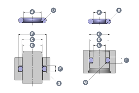
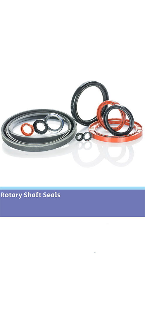
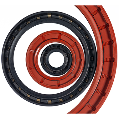
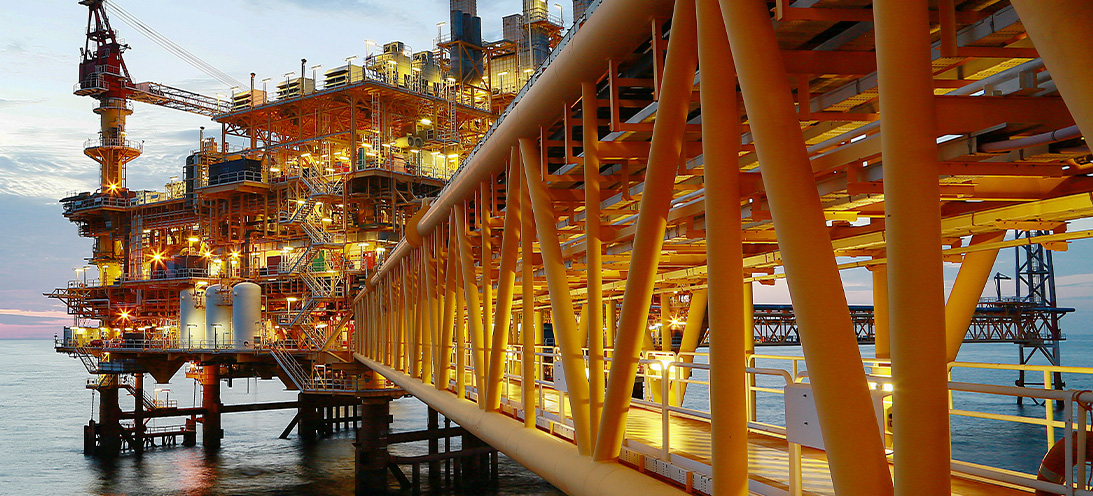
PTFE Rotary Seal for Oil & Gas drilling toolPTFE Rotary seal for oil & gas drilling tool Our customer designs and manufactures a leading range of unique downhole technology and drilling solutions that contribute to a net zero energy industry. Read on to find out about our PTFE rotary seal solution for their application. The application Our customer tasked us with developing a sealing solution for the rod of a downhole drilling tool - a hydraulic dynamic (rotary) application.The normal operating pressure was 500 PSI at 60 RPM; however, maximum pressure could reach 6,500 PSI in static operation. Reverse pressure was unlikely in this application, however, the engineers wanted to ensure some level of resistance.Two single acting seals could be considered, but specifically groove space was limited. Keeping the grooves closed was preferable for bearing strength.The maximum operating temperature could reach 200°C, additionally, the application media was drilling mud and completion fluids. The wiper arrangement was already installed. Our sealing solution Because of the pressure, temperature and chemical media parameters of this application, an elastomer seal selection was not suitable. Our engineers selected our standard FTOR profile PTFE seal. This is a double acting slipper seal ideally suited to hydraulic applications and capable of sealing under alternating pressure directions. It's ideal for sealing high pressure loads with slow to moderate rotational speeds. The PTFE seal has side wall notches equally spaced, therefore the part can be fitted symmetrically either way.The initial sealing force is provided by the elastomer O-ring. This is seated within a machined saddle and activated by system pressure to perform under high pressure demands.The sealing set was also designed with a scarf cut PEEK back-up ring to ensure stability and seal performance at maximum working pressure of 6,500 PSI. Customer satisfaction Our customer tested the sealing arrangement at higher pressure (up to 10,000 PSI). They were pleased to find it sealed successfully over and above the application requirements. They have adopted this seal design for other sizes of parts in similar equipment.
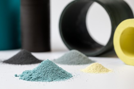
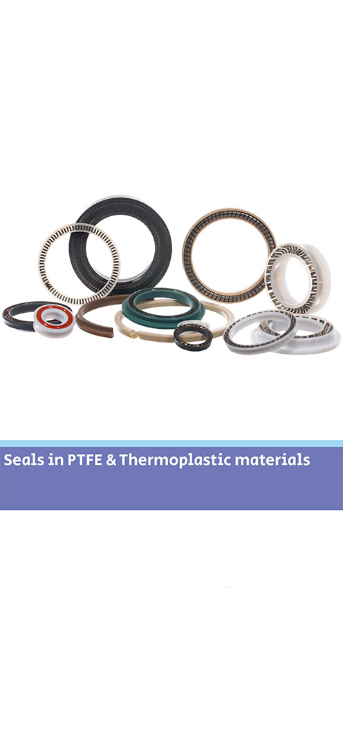
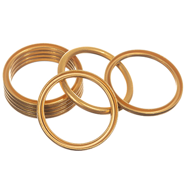
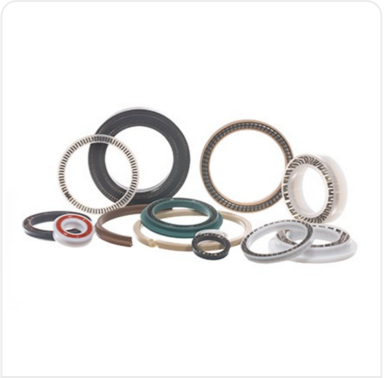
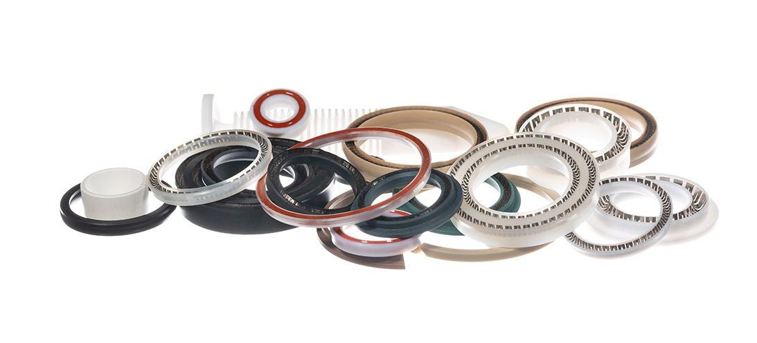
PTFE Rotary Seal for Oil & Gas drilling tool Why use PTFE seals?Why use PTFE seals? Polytetrafluoroethylene (PTFE) is a thermoplastic polymer. PTFE seals can be used in a variety of sealing applications. It’s suitable when application conditions exceed parameters of elastomeric seal use but not to the extent of a metal seal. What is PTFE? It has a high melting point (342 °C) and morphological characteristics. These allow seal components made from virgin PTFE to be used continuously at service temperatures of up to 260 °C. With the addition of fillers – up to 300°C. It has the unique ability to resist material degradation, heat-aging and alteration in its physical properties during temperature cycling. Alongside this rare combination of material characteristics, PTFE also has unlimited shelf life. Why use PTFE seals? Notably PTFE demonstrates extraordinary chemical resistance. The intrapolymer chain bond strengths preclude reactions with most chemicals, thereby making it chemically inert at elevated temperatures and pressures with virtually all industrial chemicals and solvents. Only a few media (some molten alkalis) are known to react with PTFE seals making them the perfect sealing solution for highly aggressive chemical applications.PTFE also has the lowest friction coefficient of any known solid. It has self-lubricating capabilities which offers continuous dry running ability in dynamic sealing applications and has superb stick/slip capabilities. Focus on dry coatings The advantages of using PTFE in sealing applications are multiple:Functionality at high and low temperaturesDynamic sealing with high wear capabilitiesHigh pressure sealing (using combinations of PEEK back-up rings)Compatibility with highly aggressive chemical combinations.Our range of PTFE seal products include back-up rings, rod and piston seals, slipper seals and spring energised seals in a wide variety of sizes. Materials depend on application requirements. However, we offer a wide range from Virgin PTFE or including filler combinations of MoS2, glass, carbon, carbon fibre, graphite, and bronze.These characteristics make PTFE seals perfect for the demanding applications involved in Oil & Gas, Aerospace, Automotive and Chemical Process markets (to name but a few). Ceetak’s engineering team are experienced in the design of PTFE sealing solutions to meet the complex specifications these types of application demand.Read our overview and more detail about PTFE seals HERE
Why use PTFE seals?