Surface finish requirements for static and dynamic sealingWhat is hardware surface finish?
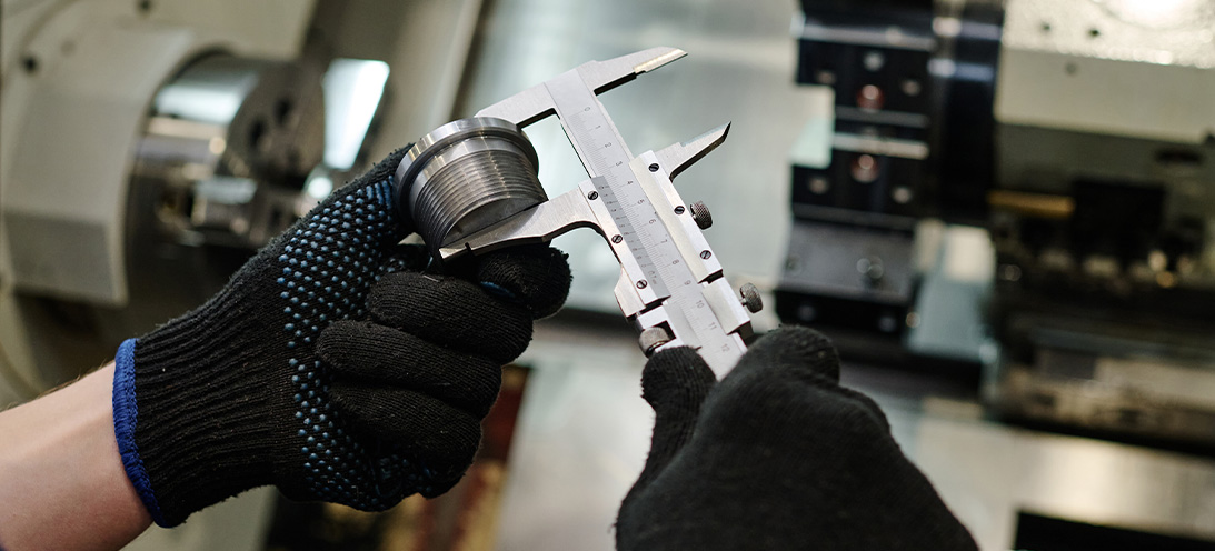
Any surface can look (and even feel) perfectly smooth. However, look closely enough with high magnification and all surfaces will have a degree of fluctuation. The topography will look similar to a mountain range or the surface of the moon! The way a surface is produced or machined, along with any subsequent processes such as coating or plating, often determines its roughness. Just a couple of decades ago, the standard approach to assessing surface finish was to use comparison plates. These small specimen sections were made by turning, grinding, or milling the material. Inspectors would then run a fingernail across the finished part and the plates to determine which one matched most closely.
What is Ra?
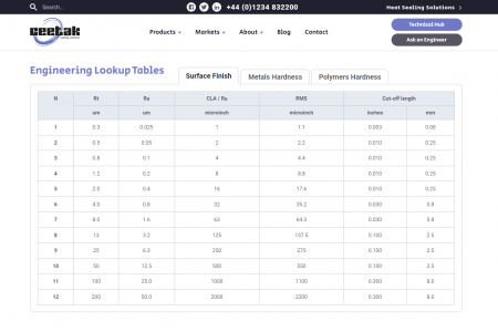
Historically, seal catalogues typically recommended a surface finish using just the Ra (metric) or CLA (Centre Line Average, inches) parameter. Little regard was given to what the seal was being expected to do. Ra simply, is the mean roughness. The average calculated from the peak heights and valley depths. A surface that is mostly spiked can have the same Ra value as one that is mostly troughed. However, each could have a very different impact on seal performance. Today, surface finish measuring equipment is more sophisticated. It’s capable of tracing a surface finish using a diamond tipped stylus, or non-contact 3D laser scanning. These devices are now reasonably affordable and provide a sophisticated level of results from essentially a portable machine. Consequently, these instruments can now analyse the surface roughness profile, trace, also calculate a large range of parameters that define that profile. This includes Ra, Rt, Rz, Rmax, Rmr (bearing ratio) and even skewness parameters. What these are, and how they should be measured, have generally been well captured in standards. These standards include ASME B46.1, ISO 4287, ISO 4288 and the upcoming ISO 21920.
Why is surface finish important for sealing systems?
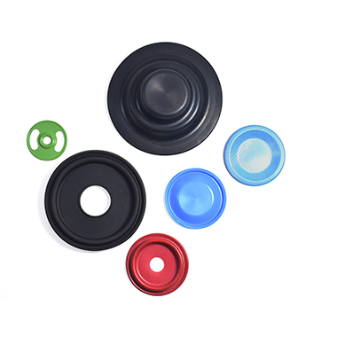
To ensure seal effectiveness, a common assumption for specifying a hardware surface finish is the smoother the finish the better. However, this is not always the case. If the seal application is static and is sealing a low molecular size gas such as helium; then a very smooth surface would be preferable. This is often referred to as a “closed” surface (with no peaks and very few, shallow valleys). The seal mates tightly against the hardware, ensuring the leak path for the gas is reduced as much as possible. Even in this scenario, the required surface roughness can be influenced by other factors. These include the hardness (or rather, softness) of the seal material and the pressure being applied, both by the initial seal squeeze and the applied gas pressure. It’s important the interface between the seal and the hardware is well lubricated. This is critical for some dynamic applications for either seal friction (and hence noise, vibration and heat) or wear life. This is partly achieved by ensuring that the surface is more “open”, with small valleys or troughs to trap the lubricant -but no sharp peaks that would abrade the seal material. In these application cases, if the dynamic hardware surface (rod, shaft or piston bore) is too smooth, then the seal can wear prematurely. This can cause juddering, squeal and excessive heat build-up.
Tribological performance consideration
As a result, for dynamic applications it is important to consider all the factors affecting the tribological performance. These include the seal (design, material), the dynamic hardware (hardness, material type) and the fluid (viscosity, lubricity, contamination). The hardness of the dynamic hardware can also be a significant factor. Hardened or chromed steels around the 50 Rockwell C level or less can often be polished by the seal itself. Therefore, even if the initial roughness is sub-optimal, good sealing performance is achieved after a brief period of bedding in. With the use of high hardness coatings such as HVOF and DLCs, the much softer seal material is very likely to be abraded by the hardware. In these cases, it’s essential to ensure that the optimal surface finish is met. This often requires a finer finish prior to the coating process. This is because coatings can be rougher than the substrate material, and post-process polishing is challenging with such hard coatings.
Any other factors to consider?
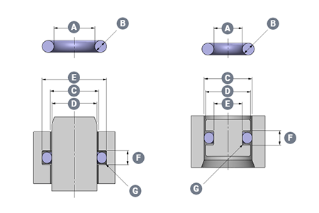
Yes! Another thing to consider is the direction (or lay) of a particular surface finish. Machining marks, scratches, dents or other hardware damage that cut across a sealing contact face are likely to result in leakage. This is compared to (for example) concentric machining marks in the base of an axial face-seal O-ring groove. It is important to consider specifying a lay direction when applying surface finish requirements to the hardware design specifications and drawings. What hardware surface finish should you specify?
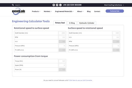
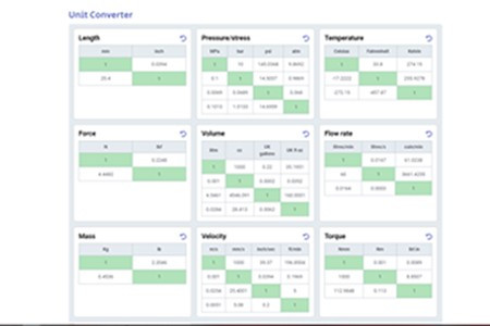
Despite complexities involved in hardware surface topography, the sealing industry has developed a comprehensive set of recommendations. These can vary a little between different manufacturers and suppliers. Given the specificity of the seal design and material, they’re best found within the specific literature for the products considered for the application. This is a good starting point, but for each individual application it’s worth considering whether these specifications should be addressed. For example, specifications could be tightened, or perhaps even loosened to ensure that performance targets can be met. This would reduce the need to over-specify the surface finish – because this can add unnecessary processing cost to a part. The practicalities involved in accessing the surface to measure also need consideration. It’s notoriously difficult to check the sidewalls of an O-ring groove, especially in a rod/ID sealing configuration. Cylinder bores are often less tightly defined due to stylus/probe access issues compared to rods and shafts. Importantly, anyone producing and checking a particular surface finish must have both the equipment and the understanding to do so. This is very important if using relatively modern and less well known parameters such as Rmr (or Tp, bearing ratio). Further detail can also be found in the ISO and ASME standards regarding measuring settings. For example, filtering/cut-off values, stylus tip radius, measuring, evaluation and tracing lengths. When validating a supplier’s measurements, it’s important these machine settings are identical. Failure to do so will result in differing surface finish values obtained on the same part. Those standards are not specific to sealing applications. Generally, we’d recommend a cut-off filter (λc) of 0.8, unless measuring very fine (< 0.1 µm Ra) surface finishes where 0.25 would be more suitable, with a 2 micron stylus tip in all cases.
Engineering expertise
Specifying the right surface finish for the hardware components that contact a seal can be complex and daunting. We will ensure an optimum finish and right-first-time seal performance. This is with our core understanding, and consideration of relevant parameters for the given application. For more on our engineering expertise, read HERE

Surface finish requirements for static and dynamic sealing 
Using Finite Element Analysis (FEA) in seal designUsing Finite Element Analysis (FEA) in seal design Finite Element Analysis (FEA) is a computerised modelling method for predicting how an object reacts to forces, whether directly applied or generated by pressure, temperature effects or vibration. FEA provides data to help predict how a product will function under those applied conditions. Additionally, it identifies areas where the design can be optimised and improved, without having to test multiple prototypes.Our specialist software uses mathematical models to understand and quantify the effects of real-world conditions on a part or assembly. It can be used to identify potential causes where sub-optimal sealing performance has been witnessed and can also be used to guide the design of surrounding parts. Importantly for products such as diaphragms and boots where contact with adjacent parts may need to be avoided. The software also allows force data to be extracted . For example, compressive forces for static seals and friction forces for dynamic seals can be accurately predicted to help our customers in the final design of their products. Why do we use Finite Element Analysis (FEA)? Our engineers encounter many sealing applications that are critical and have many complicating influences. Envelope size, housing limitations, shaft speeds, pressure/temperature ratings and chemical media are all application parameters that our engineers must consider when designing a seal.In isolation, the impact of these application parameters is reasonably straightforward to predict when designing a sealing solution. However, when you compound a number of these factors (whilst often pushing some of them to their upper limit when sealing) it is crucial to predict what will happen in real application conditions. Using FEA as an iterative tool, our engineers can confidently design and then manufacture robust, reliable and cost-effective engineered sealing solutions for our customers.Starting with a 2D or 3D model of the initial design concept, produced within our advanced CAD system, we then apply the boundary conditions and constraints supplied by the customer, including pressure, force, temperatures, and any applied displacements. A suitable finite element mesh is overlaid onto the seal design, ensuring that areas of most interest have the necessary mesh size to ensure accurate results are returned for these regions whilst utilising larger mesh sizes in areas with less relevance or lower levels of displacement to minimise the computing time required to solve the model.Material properties are then assigned to the seal and hardware components. Most sealing materials are non-linear, whereby the amount they deflect under an increase in force varies depending on how large that force is, unlike the straight-line relationship for most metals and rigid plastics, at least over the displacement range relevant to sealing applications. This complicates the material model, and extends the processing time, but we use in-house tensile test facilities to accurately produce the stress-strain material models for our compounds to ensure the analysis is as representative of real-world performance as possible. What happens with the FEA data? The analysis itself can take minutes or even hours of computing time, depending on the complexity of the part and the range of operating conditions being modelled; behind the scenes in the software, many hundreds of thousands of differential equations are being solved.The results are then analysed by our experienced seal designers to identify areas where the design can be optimised to match the specific requirements of the application; such requirements may be for sealing at very low temperatures, a need to minimise friction levels with a dynamic seal, withstand very large pressures without extruding, or whatever sealing system properties are most important to the customer and the application.Results for the finalised proposal can be presented to the customer as force/temperature/stress/time plots, numerical data or animations showing how a seal behaves throughout the analysis, as appropriate to their needs, and can be used as validation data in their system design process. Project 1 case study Faced with very tight packaging constraints, a customer requested a diaphragm component from us for a valve application. Using FEA, we were able to optimise the design not only of the elastomer diaphragm itself, but also propose modifications to the customers hardware components that interfaced with it in order to increase the available space for the diaphragm, keeping material stress levels low to remove any possibility of fatigue failure of the diaphragm over the life of the valve. Project 2 case study A customer approached us to design a PTFE rotary lip seal that had to meet tight maximum torque requirements as their system was driven by a size-limited low power motor with modest levels of torque available.At the same time, high seal tightness was required as leakage of the media would have caused significant problems.By using an iterative FEA process, we produced a seal design that optimised the sealing lip geometries to provide the lowest levels of rotational friction drag whilst ensuring sufficient contact force to maintain a tight seal, and went on to provide seals that successfully passed customer validation testing.With the increased confidence in a proposed sealing solution that FEA provides, our customers can plan lower levels of physical testing and remove contingency for re-design steps, reducing their project lead times and costs, facilitating a faster and more cost-effective time to market for their new products.

Using Finite Element Analysis (FEA) in seal design Are all elastomers the same?Are all elastomers the same? Material hardness This is often the least considered property when selecting a material. In sealing applications, elastomer material hardness can impact assembly loads, seal friction and extrusion resistance. Softer rubber can better accommodate surface imperfections (especially when sealing low pressure gas). This means softer seal compounds can be used effectively against rough hardware surface finishes. Harder compounds will have greater wear resistance in dynamic applications.Most of the common base elastomers are produced in 60 to 80 Shore hardness range. These tend to be produced in increments of 5 hardness points. It's important to remember the hardness tolerance of a material is typically +/-5 points, therefore 70 and 80 hard nominal materials could both legitimately have a hardness of 75 Shore A.With possible hardness down to 30 Shore A (or even lower), silicone rubber lends itself to applications requiring very soft seals. An example of which is where seal compression forces need to be low to enable easy manual assembly of components. NBR, HNBR and FKM materials can be formulated up to 95 Shore A hardness for highly demanding high pressure and temperature applications; for example applications found in the Oil & Gas industry. Chemical compatibility Unlike PTFE seals (given very few chemicals that will attack and breakdown the material) elastomer seal materials must be carefully selected. This is so the properties are not affected by any fluids or gasses that the seals come into contact with. This includes the main media that the seal is retaining or excluding, additionally any contaminants (such as cleaning fluids or bi-products of reactions between any of these fluids, the seal material or the surrounding hardware).Even a seemingly straightforward application often involves a long list of chemicals and compatibility must be checked with the elastomer. Most seal suppliers publish compatibility tables or like us, have interactive tools to help check this. Even then, it’s often not the brand name oil that’s listed. For example, often at the more basic chemical level, so some knowledge of what’s actually in the fluid is required. Recent developments in health, safety and environmental requirements have made this a little easier. However, some fluid manufacturers can still be a little reluctant to declare the full list of chemicals in their products.Manufacturers sometimes give guidance on general compatibility with elastomer groups, but this can be a little generic. Additionally, not all grades in a specific group will have the same resistance to a particular fluid. Again, this can be especially relevant to NBRs and HNBRs with a variable ACN content. Sometimes the reactions can be dramatic and swift, with the rubber shrinking or swelling in a matter of hours when exposed to a non-compatible fluid and especially at elevated temperatures where the chemical reaction is accelerated. Reactions in chemicals In other cases, the reaction could be slower, but still causes sealing issues resulting in earlier system failure compared to using more capable elastomers. This is often the case with FFKM seals in applications where the cost of replacement or downtime is very high. The outstanding chemical resistance of these materials gives considerably longer service life compared to lesser grades, and it justifies the higher initial cost of the seal. In other cases, some reactions can be beneficial, for example where a small amount of elastomer seal swell in an oil over time can help to offset wear in dynamic O-ring energized PTFE slipper seals. Temperature range Outwardly, this material property seems straightforward, but elastomer technology is rarely that cooperative. All elastomer compounds will have a low temperature property stated on their datasheet. Either the TR10 (temperature at which a stretched and frozen sample recovers by 10% of its length) or the Tg (the glass transition temperature, at which all flexibility is fully lost).However, applied pressure increases the Tg by approximately 1°C for every 5 MPa. This is significant for even moderately high-pressure applications. Additionally, the flexibility required for successful sealing will vary between applications, making the correct material selection critical. At the other end of the spectrum, elastomers respond poorly when exposed to temperatures above their capability. This results in the material suffering irreversible degradation that reduces seal performance.Whilst guidance is given on maximum temperature capability for any specific elastomer grade, this is often in a benign air environment. Therefore the chemical impact of being exposed to hot fluids in the sealing application should be considered.Material groups tend to have well published temperature ranges. For example, the silicone family is able to reach -100°C (or even lower with special grades), and perfluoroelastomer (FFKM) grades are able to withstand 320°C (or even higher for short durations).Confusingly though, considerable variations can exist even within the same material families; especially with FKM where the more modern grades can now reach down to -50°C, with older technology grades only capable of -15°C. There are many NBR and HNBR grades where the acrylonitrile (ACN) content can be varied so that the low temperature limits can be between -30°C and -60°C, depending on the specific recipe formulation.This is just a short summary of three properties of elastomer materials. It’s clear that selecting the correct grade of material for a specific application is a difficult task, yet one that is absolutely critical to achieving the seal performance and lifetime required.
Are all elastomers the same? The importance of engineering tolerancesThe importance of engineering tolerances What tolerances are we concerned with? We can start with the seal itself, and specifically the seal material, as almost all polymer seal materials contain multiple ingredients. For PTFE and polyurethanes this is typically 2 or 3 different elements. However, for an elastomer material as many as 30 different ingredients can be used in the recipe. Each ingredient is weighed or measured before being added to the mixing machine, with a tolerance on the mass or volume of the solid or liquid ingredient.Digital advances in weighing and dosing equipment have improved tolerance ranges since synthetic rubbers were first commercially produced in the 1930’s. However, it’s important to remember that a small variation in material mix from batch to batch is inevitable.The mixing process (also now digitised to help reduce variation) is controlled by parameters which also have a tolerance. Pressures, temperatures, speeds and times are kept within certain limits and determined by the sophistication of the mixer and its control systems.To produce the finished seal, mould tools for polyurethane and elastomer seals are manufactured using CNC or electrical discharge machining techniques. These hold incredibly tight tolerances on the metal form. However, are will be variations in moulding pressure and temperature, combined with slight variations in material shrinkage rates. This results in tolerances on the finished parts that are significantly wider than the metal tool it was produced from. For machined seals, polymer seal materials tend to have high rates of thermal expansion. Together with their relative softness makes it difficult to maintain the same level of tolerance that can be achieved when machining metal components. Hardware tolerances When designing hardware for seal installation, tolerances are perhaps more obvious, and certainly where engineers can focus some attention. Plastic housings (whether injection moulded or machined), together with metal castings or pressings can pose tolerance challenges. Even for relatively straightforward machined metal housings, selecting the correct tolerance to apply is key.For many applications, a stack-up of tolerances is to be considered. This is together with tolerances of the assembly such as concentricity or misalignment (especially for dynamic sealing applications). Other considerations include bearing wear and the resulting increase in misalignment or runout as the equipment approaches the end of its target life. Why are tolerances important for sealing systems? A combination of theory and experience over decades, seal designers have developed an ideal set of installation conditions for many applications. From static flange or face sealing, through linear hydraulic cylinder seals and to rotary shaft sealing and more. Some of these applications have adopted standardised recommendations (such as ISO 3601 for O-rings and DIN 3760 for elastomer shaft seals). However, because no two applications are truly identical, many are based on the experience and preferences of the seal designer.Regardless, every application starts from a nominal condition, and the maximum and minimum tolerance conditions should always be considered. This is even in seemingly straightforward applications to ensure the seal is continuing to operate within it’s ideal set of conditions.Sometimes it’s assumed that tolerances only really come into play when looking at very small applications, with so-called “micro O-rings”. This is not the case - and we can illustrate this with a hypothetical application: A device containing a 25 mm rod, static, with an FKM O-ring sealing gas, whilst installed for 10 years untouched in the Arctic circle. However, it also needs to seal oil whilst installed in direct sun at the equator for 10 years, but with the rod removed and re-fitted several times a year. The device designer would prefer not to make two different variants.O-ring calculators working to ISO 3601 would recommend a 25.12 mm x 1. 78 mm O-ring fitted in a 27.8mm groove with f7 tolerance on the rod and H9 on the groove. However, in the cold application the worst-case squeeze is looking a little light to ensure long term gas sealing. Whilst in the high temperature location, the compression and groove fill are reaching levels that could accelerate compression set of the material and cause issues when the rod is disturbed and re-fitted.Moving the nominal sizes would help one installation but adversely impact the other. However, by tightening the tolerance on the rod and the groove, the concerns at the extreme conditions can be lessened. Approaching the seal supplier for tighter tolerance O-rings can improve the robustness of the design even further, as could incorporating a custom bonded seal-rod component which would remove one dimension and its tolerance completely. Such a hypothetical application rarely exists of course, but the approach is applicable to a surprisingly large number of applications which appear “standard” at first glance. What hardware tolerances should be specified? There is not a definitive answer to this question, but more of a recommendation that the tolerances for each component within an application are considered. Both the technical and financial impacts being evaluated. Sometimes applying a tighter tolerance can be achieved without any cost implications. In other cases it might slow the manufacturing process, or potentially require a different and more costly process (for example, grinding a rod in place of turning).Tolerances should be evaluated by the consequences of the complete sealing system not performing as intended at the absolute extremes of potential tolerance conditions. In applications where the impact of non-optimal performance may be less severe, a paper based, or theoretical tolerance evaluation is carried out. This could provide enough confidence the risk and impact of the problem arising is acceptable compared to the costs of preventing the risk further.In some safety critical applications in Life Sciences & Medical, Aerospace or Vehicle Control systems markets, testing of parts at the most extreme sizes may be required. This is to be certain that any combination of components from anywhere within their minimum or maximum range of tolerance sizes would still produce an assembly product which performs successfully in the application.To use our resources including our O-Ring Calculator, click on this link HERE
The importance of engineering tolerances Elastomer manufacturing moulding processesElastomer manufacturing moulding processes Compression moulding This is the simplest method of converting a piece of rubber into a finished seal product. The rubber compound is first mixed and prepared, and depending on the recipe can require up to 30 different individual ingredients. At this stage the curing (or vulcanization) of the rubber hasn’t yet taken place, therefore, the material has a stiff and non-elastic consistency (a little like thick dough). From this dough we produce a rubber blank (also known as a pre-form) by either cutting, punching or extruding cord. These blanks are normally a little bigger than the finished part (normally based on weight) and are placed into a metal moulding tool. The tool (in its simple form) is in two halves with the final product shape cut into the metal. This is known as the mould cavity.This “sandwich” of the bottom tool/rubber blank/top tool is placed into a hydraulic compression press with heated platens. This transfers the heat into the rubber via the metal tool. The press closes. The rubber is then squeezed into every part of the cavity, and any extra material that extrudes from the mould join becomes become overflow, or flash. Next comes curing of the material. This takes place through a chemical reaction between the ingredients, and is controlled by pressure, temperature and time. These parameters are pre-set according to the recipe of the material and the curing system. At the end of the specified cure time, the press is opened. The tool is then removed and split apart, and the cured (elastic) component is removed. Through a variety of methods, the excess flash is then detached, and the part may undergo a post-cure process. This fully completes the vulcanization reaction. Finally, the rubber seal is inspected, packaged and ready for application. The compression moulding process Compression moulding is sometimes a relatively slow and labour-intensive process. Some tools will have multiple cavities into the hundreds and use presses ranging in size and capacity from 20 tons to over 500 tons. This will increase throughput of seals, but the key limiting factor is the speed of heat transfer from the platens into the rubber via the mould tool. In-press cure times can be measured in minutes, but for large parts sometimes over 10 minutes or more. Removing the parts and loading the next set of rubber blanks can also be time consuming.Compression tools are quick and easy to produce, and changeover times from one component to another can be rapid. As a result, this manufacturing method is ideally suited to parts that are required in low quantities, or as prototypes. The tools are designed to ensure that the split/flash line is not located on a sealing contact surface. Therefore, high-quality parts will be produced.For some very hard rubber compounds that do not flow readily, compression moulding is sometimes the only manufacturing option. Injection moulding This is the simplest method of converting a piece of rubber into a finished seal product. First, the rubber compound is mixed and prepared. Depending on the recipe, there can be up to 30 different individual ingredients. At this stage, the curing (or vulcanization) of the rubber hasn’t yet taken place. Therefore, the material has a stiff and non-elastic consistency (a little like thick dough). From this dough we produce a rubber blank (also known as a pre-form) by either cutting, punching or extruding cord. These blanks are normally a little bigger than the finished part (normally based on weight) and are placed into a metal moulding tool. The tool (in its simple form) is in two halves with the final product shape cut into the metal. This is known as the mould cavity.Elastomer materials need to be specifically formulated for injection moulding to give them the required flow characteristics. The tooling is also significantly more complex compared to compression or transfer tools, especially with multi-cavity tools and cold runner blocks to reduce the waste in the sprue and runner system. Set-up times somewhat longer. Machinery In terms of machinery, injection presses are also more complex and costly than hydraulic compression presses, but the injection moulding process can be highly automated. This, in conjunction with fast cycle times can result in very attractive manufacturing costs for parts produced in high volumes. As with the transfer process, the flow of the rubber into the cavity can be designed to reduce the risk of air trapping and give consistent material properties in the finished part. Transfer moulding This is a variation on compression moulding. It uses the same hydraulic compression presses, but this tooling is a little more sophisticated (and consequently a little more expensive).Rather than loading the rubber blank direct into the cavity it’s held in a “well”, and the top tool part contains a plunger which squeezes the rubber though feed ports/gates into the cavity below. By using this approach, the cavity is closed before the rubber enters. This reduces the amount of flash left remaining on the part, and allows accurate positioning of metal or plastic inserts for two-part bonded components.The material may need to be specifically formulated to allow it to flow through the feed gates. The result can be a more uniform part using this flow of rubber, compared to a compression moulded part where some of the rubber has not had to flow very far during the tool closure. The part and tool can be designed so that the direction of this flow acts to expel the air from the tool and prevent it becoming trapped by the rubber in the middle of the part (which can sometimes be an issue with compression moulding).Tolerances, accuracy and consistency are improved compared to compression moulded parts but the cycle time, or throughput, is broadly the same.There are other ways to manufacture rubber parts, including extrusion, calendaring and even 3D printing, but from comparing the three most common methods of producing an elastomer seal, we can see that considering how the part is going to be made at the start of the project is key to ensuring the technical and commercial success of the seal in the application.

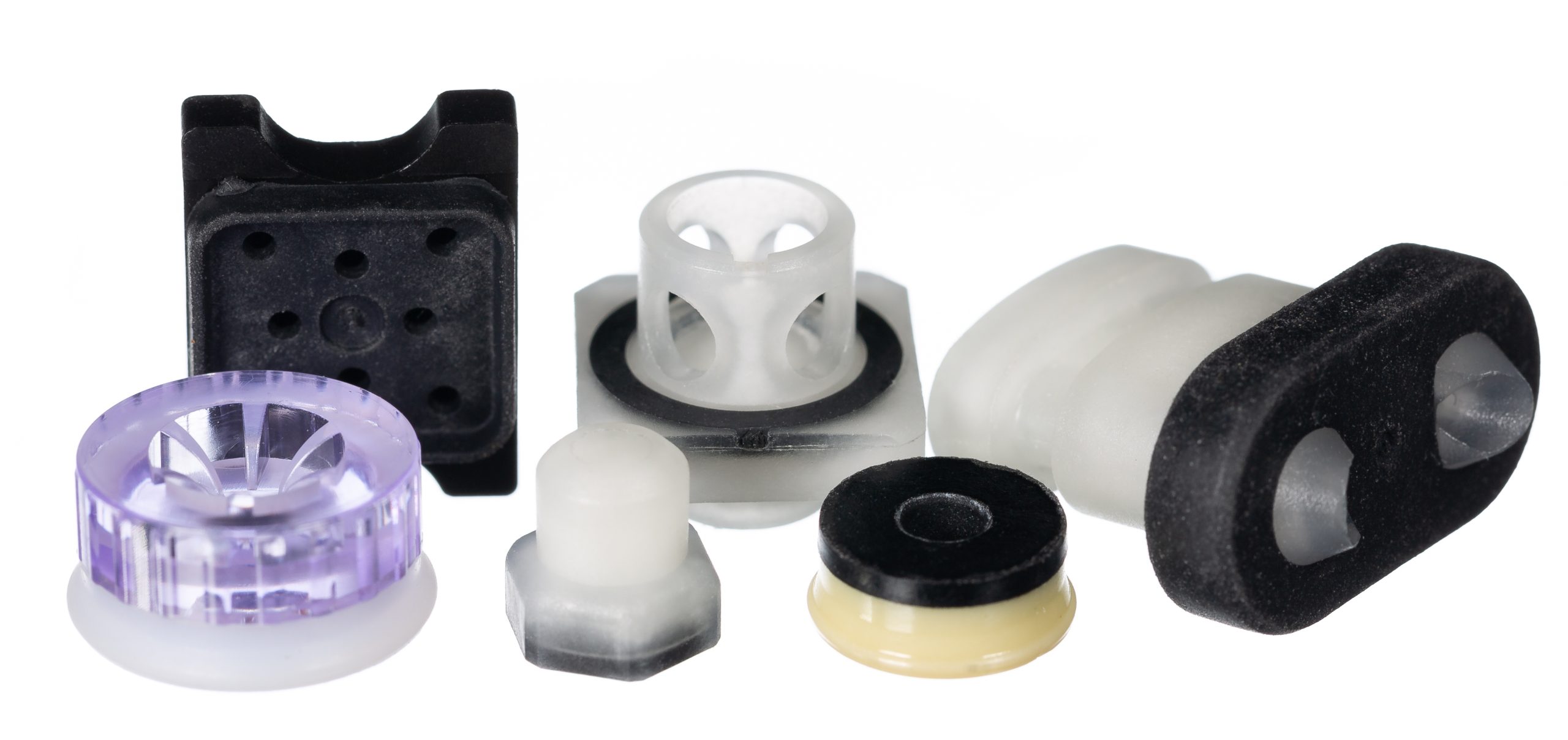
Elastomer manufacturing moulding processes Polyurethane as a seal materialPolyurethane as a seal material The foam in your armchair. The strap on your wristwatch. The wheels on a supermarket shopping trolley and beyond; Polyurethane certainly has a diverse range of uses since its invention almost 85 years ago. Aside from day-to-day products; it is also a highly capable and versatile sealing material - and an option that is often overlooked.
Here we explore a little deeper into the properties of polyurethane. Covering it's uses as a seal material and how it is manufactured. What is polyurethane?Is it rubber? Is it plastic? Rigid or flexible? The answer to all of those questions is – yes, it is all of these things! Polyurethane covers a group of materials; plastic polymers produced by the combination (or synthesis) of di-isocyanates with polyols and a chain extender.Thermoplastic Polyurethane (TPU) belongs to the Thermoplastic Elastomer (TPE) family. It was originally invented by Otto Bayer in 1937 and further developed during WWII as an alternative to rubber (which was difficult to source at the time). It can be formulated to produce different finished materials with an array of properties suitable for a wide range of applications. Where do we use polyurethane? In addition to seals, polyurethane is the basis of a diversity of products. These include varnish, foam mattresses, roller skate wheels and surfboards. There are literally hundreds of different types of polyurethanes, each made in a slightly different way to suit the demands of the final product. How are polyurethane materials manufactured? In a one-step process, the polyol (a compound containing multiple hydroxyl groups) is mixed with isocyanate (highly reactive low molecular weight chemicals) and a chain extender (low molecular weight diols or diamines). The result is a random copolymer with a physically cross-linked irregular molecular structure.In a two-step process, the polyol and isocyanate are mixed first to produce a pre-polymer. This is then mixed with the chain extender to produce a block copolymer with more regular molecular structure. This can result in improved and more consistent material properties in exchange for a slightly higher production cost.We use rigid polyurethanes for sealing products. The mixed liquid material is either cast into tubes from which seals can be machined on CNC lathes. Alternatively cast into bricks which are then chipped, mixed with dye (or other additives), and fed into injection moulding machines. Why is polyurethane a good seal material?When formulated appropriately, polyurethane yields an impressive set of material properties that make it an ideal material for sealing products. It can be flexible which allows seals to be assembled into closed grooves. This capability also resists large deformation and makes them robust to survive without damage. In this respect it outperforms PTFE and is at least on a par with rubber.Polyurethane has excellent elastic behaviour, recovering almost instantly from deformation. Again, outperforming PTFE (no springs or rubber energisers needed to give the initial sealing contact stress) and matching rubber materials. However, unlike rubber it has a lower coefficient of friction, with very high abrasion resistance, tensile strength and stiffness. These properties mean it is often used without anti-extrusion/back-up rings at considerably higher pressures than even a 90-durometer elastomer O-ring would be capable of. How does polyurethane perform in tests? In abrasion tests, polyurethane has a quarter of the wear rates shown by typical rubber sealing materials. These include NBR (and considerably lower than even filled grades of PTFE). Its tensile and tear strengths are typically 3-5 times higher than rubber seal materials. Although it lacks the chemical resistance and temperature capability of PTFE, it is compatible with mineral oils.Polyurethane seal materials typically have a general operating temperature range of around -35°C to +110°C. However, more specialist grades can remain flexible down to -50°C, and other grades can push the upper limit to around 130°C.Because it can be injection moulded as well as machined from tubes, it lends itself to production of seals in both high and low quantities. This allows commercial flexibility at both prototype and production stages of a project.With complex chemistry, care must be taken to ensure sealing fluid resistance and temperature capabilities are always considered (as is the case when selecting any seal material). However, in many applications, polyurethane can often bring physical property and whole-life cost advantages over rubber or PTFE options. This can mean it bridges the gap in capabilities between these material groups.

Polyurethane as a seal material Why the focus on PFAS?Why the focus on PFAS? PFAS is a blanket term used to describe Poly- and Per- fluoroalkyl substances. There are currently around 10,000 substances in existence that fit this description, with potentially more variants still yet to be produced. Some are already known to be harmful to human and animal health and the environment (such as PFOA and PFOS), and these specific PFAS are already controlled under legal restrictions. But in February 2023, The European Chemical Agency (ECHA) published a regulatory proposal to further restrict the manufacture, placing on the market, and use of all PFAS within the EU. What are the consequences for seal manufacturers? A broad ban on all PFAS would have a significant and direct impact on European industries and businesses that manufacture products using these substances; and will have consequences globally.One particular concern is the fluoropolymers material group. These elastomers could be caught in any blanket ban of PFAS without any exemption.These materials are essential in a wide variety of applications in the food, medical, pharmaceutical, clean energy, semiconductor, electronics, oil & gas, chemical, automotive and electric vehicle industries.These fluoropolymers include materials used in high performance sealing solutions, such as PTFE and PVDF plastics, and FKM, FFKM and FVMQ elastomers. What's the problem? There is substantial scientific evidence to show that fluoropolymers demonstrate unique characteristics that mean they do not pose significant risk to the environment, or to human health as they’re not bio-available, toxic or mobile.They do not dissolve in or contaminate water, or generate microplastics, and as a result cannot enter or accumulate in a person’s bloodstream.They meet the criteria specified by the Organisation for Economic Cooperation and Development (OECD) as “polymers of low concern” as they present no significant toxicity concerns, and do not degrade into other PFAS chemicals.Fluoropolymers far outperform other sealing materials in countless applications. To put it simply; they seal tighter, last longer and survive harsher application environments considerably better than any other available materials. Fluoropolymers add irreplaceable value to society, and contribute significantly to environmental sustainability. What do we do? We fully support restricting the use of PFAS chemicals that are known to be harmful to our health or our environment; but we believe grouping all PFAS within a restriction would be a mistake.Fluoropolymers do not have the toxicological and environmental profiles of other PFAS, and prolonged existence alone is not justification to restrict a substance under REACH.We already work proactively to ensure the products we put to market are safe, compliant with legislation, and utilise the latest sustainability developments to minimise our impact on the environment – during manufacture, in use and at end-of-life. As a company with high environmental, social and governance standards we will continue to do so, whenever and whatever new legislation comes into force.But we believe the sealing industry, it’s many customers, end users and indeed society as a whole, need specific derogations and exemptions for fluoropolymers (free of any time limitations) to be included in any legislation covering PFAS substances.To learn more about our key industries and our sealing solutions, read HEREAs we have done, we strongly encouraged any individual or organisation that may be impacted by a ban to engage with ECHA during their consultation period on this proposed restriction (which ended on 25th September 2023).

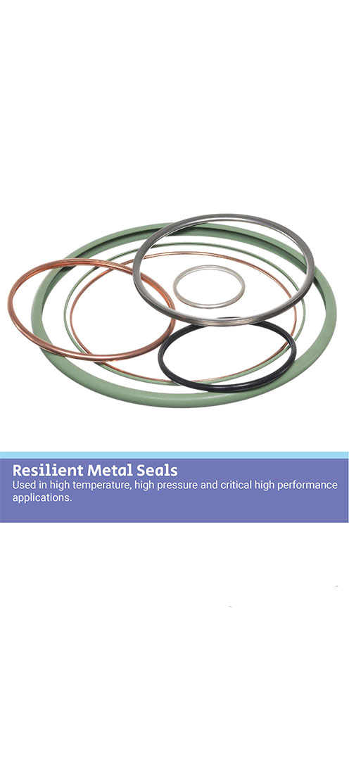
Why the focus on PFAS? Seals for cryogenic applicationsSeals for cryogenic applications Cryogenic sealing means controlling or sealing a media at very low temperatures. This process can be complex and advanced, and spans a range of markets; from pharmaceutical, chemical and refrigeration, to automotive and electronics. What are low temperatures for seals? A typical industrial sealing system will operate in the realms of a stable temperature rating. This is often sufficient for elastomer seals to cope with most of the time. For example, a general pump application running at -20°C to +80°C in air or water is perfectly suitable for a sealing solution manufactured in nitrile (NBR) elastomer. However, if a temperature specification dropped to -196°C in liquid Nitrogen; the sealing solution would have to be adapted dramatically. This would be changed to a more advanced polymer sealing solution. This is because general elastomer groups such as NBR, FKM, & VMQ are simply not suitable to perform at very low temperatures. This is attributed to the chemistry of the elastomers at a molecular level.All elastomers need a particular chemical makeup to be able to withstand a temperature range of the application. However current global elastomers on the market are not rated much more below -70°C. This means elastomers are not a viable choice for cryogenic applications with temperatures below -70°C (often requirements reach -196°C or lower). Types of cryogenic sealing solutions Specialised sealing solutions are required for cryogenics conditions. Here at Ceetak, our engineers utilise a range of more advanced seal polymers to solve the most demanding and critical application setups.PTFE is often a go-to material due to its outstanding temperature rating of -260°C to +260°C and low friction characteristics. Additionally, it’s often used in conjunction with a metal spring energiser.The spring energiser acts to maximise the sealing force at the seal contact points and to maintain a tight seal. This is even when the very low temperature conditions are attempting to contract the seal away from the mating surfaces.Other common polymers suitable are UHMPWE and PTCFE for more specific applications. Our seals for cryogenic applications We offer a range of cryogenic sealing solutions for various markets and applications including; pumps, engines, couplings, cylinders and many more.Read about our full range of engineered materials HERE

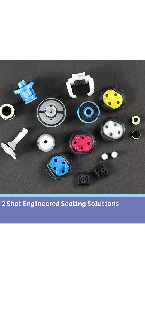
Seals for cryogenic applications Why use 2-Shot moulded seals?Why use 2-shot moulding? 2-Shot moulding is a manufacturing process that allows the co-polymerisation of hard (or soft) plastics and thermoplastic elastomers (TPE’s). We use the 2-Shot manufacturing approach to deliver engineered parts that perform a critical sealing function. What is 2-shot moulding? A 2-Shot mould is designed with a top and bottom cavity. During the moulding process the first material is injected into the top cavity and the mould opens and rotates. The first material is then injected into the top cavity again, while the second material is injected into the bottom cavity simultaneously. The mould then opens, and the parts are ejected from the bottom cavity. The mould rotates again and the whole process is repeated.2-Shot moulding is not considered a brand-new method of manufacturing. Actually, it has been used for years to produce items that we see and use every day. For example, toothbrushes, tools, kitchen utensils and toys are produced by multi-shot moulding. These are relatively cheap items in large production quantities. Why do we use 2-shot moulding? Previously, manufacturers of high volume metal or plastic- to- rubber component assemblies have processed them via chemical or mechanical bonding. This was by using adhesives or over-moulding. Markets that lend themselves to these types of sealing products are Automotive, Life Sciences and Aerospace & Defence.Although these production methods may achieve the final assembly requirement, the many different processes involved are lengthy, costly, and can be fraught with problem areas that require stringent controls. A failure in any of these areas will result in poor quality parts, therefore often deeming these methods unsuitable for critically engineered components. Why do we use 2-shot moulding? When designing a new 2-shot moulded product (or replacing an existing assembly part) our engineers review each application parameter carefully. They utilise years of sealing experience and materials expertise alongside the latest 3D modelling technologies. This is accompanied with FEA simulation programs -all before presenting a seal proposal. This allows us to anticipate and analyse the finest details of mould performance and means we can adjust our seal design if required. This is to ensure our customers receive the highest level of performance possible from our engineered 2-shot seal solution.The result means we supply our customers with high integrity parts with a powerful molecular bond. Additional benefits include reduced production cycle times (because additional processes are removed from the production line) and comprehensive cost reductions. This is because all parts are produced in a single manufacturing tool (meaning reduced running costs and the removal of pre and post moulding processes).2-Shot moulding is not just a way of simplifying the manufacture of multi-material parts in high volume. Our application engineers are constantly breaking norms and pushing design limits. We are proud to consider more creative ways of producing high performance engineered sealing solutions to meet our customer requirements.Read more about our 2 shot mouldings HERE
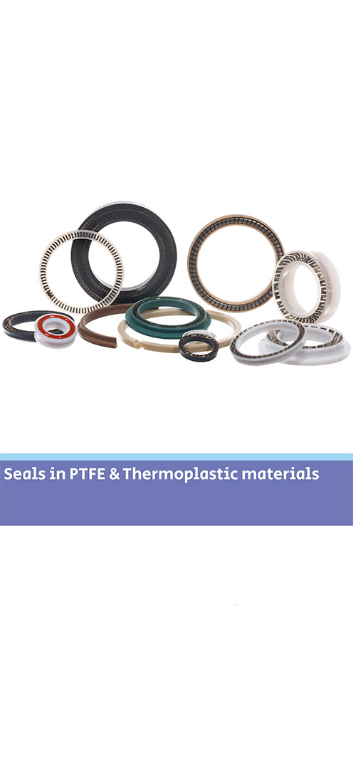
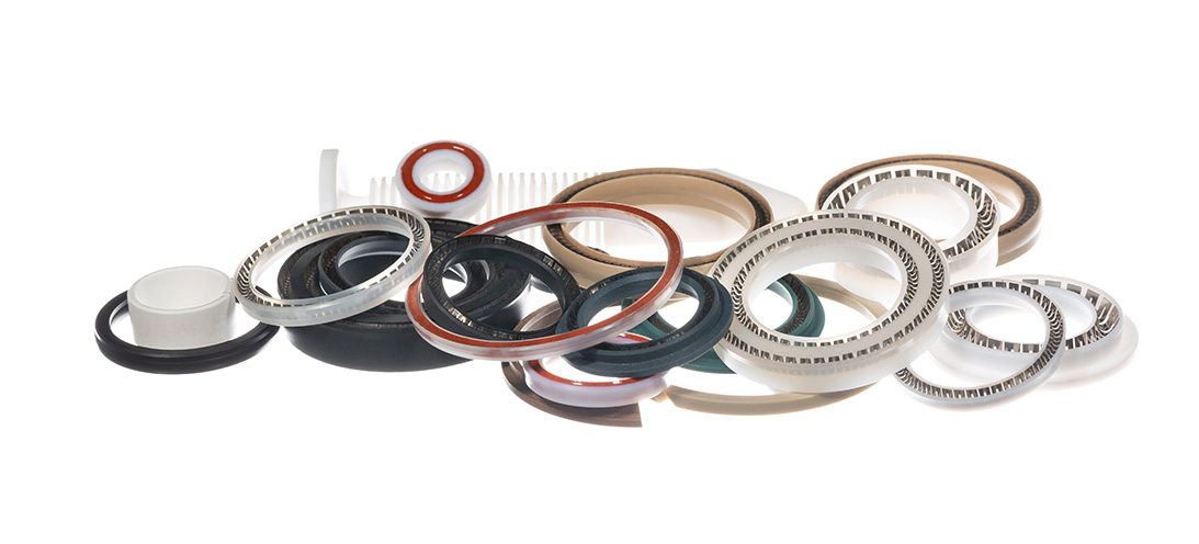
Why use 2-Shot moulded seals? Why use PTFE seals?Why use PTFE seals? Polytetrafluoroethylene (PTFE) is a thermoplastic polymer. PTFE seals can be used in a variety of sealing applications. It’s suitable when application conditions exceed parameters of elastomeric seal use but not to the extent of a metal seal. What is PTFE? It has a high melting point (342 °C) and morphological characteristics. These allow seal components made from virgin PTFE to be used continuously at service temperatures of up to 260 °C. With the addition of fillers – up to 300°C. It has the unique ability to resist material degradation, heat-aging and alteration in its physical properties during temperature cycling. Alongside this rare combination of material characteristics, PTFE also has unlimited shelf life. Why use PTFE seals? Notably PTFE demonstrates extraordinary chemical resistance. The intrapolymer chain bond strengths preclude reactions with most chemicals, thereby making it chemically inert at elevated temperatures and pressures with virtually all industrial chemicals and solvents. Only a few media (some molten alkalis) are known to react with PTFE seals making them the perfect sealing solution for highly aggressive chemical applications.PTFE also has the lowest friction coefficient of any known solid. It has self-lubricating capabilities which offers continuous dry running ability in dynamic sealing applications and has superb stick/slip capabilities. Focus on dry coatings The advantages of using PTFE in sealing applications are multiple:Functionality at high and low temperaturesDynamic sealing with high wear capabilitiesHigh pressure sealing (using combinations of PEEK back-up rings)Compatibility with highly aggressive chemical combinations.Our range of PTFE seal products include back-up rings, rod and piston seals, slipper seals and spring energised seals in a wide variety of sizes. Materials depend on application requirements. However, we offer a wide range from Virgin PTFE or including filler combinations of MoS2, glass, carbon, carbon fibre, graphite, and bronze.These characteristics make PTFE seals perfect for the demanding applications involved in Oil & Gas, Aerospace, Automotive and Chemical Process markets (to name but a few). Ceetak’s engineering team are experienced in the design of PTFE sealing solutions to meet the complex specifications these types of application demand.Read our overview and more detail about PTFE seals HERE
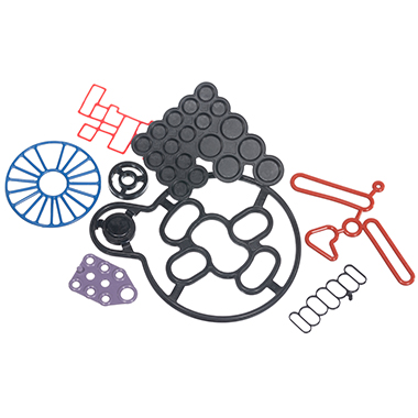
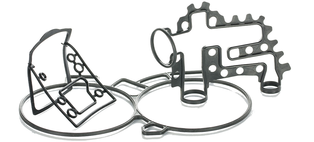
Why use PTFE seals? Why use Push-in-Place gaskets?Why use Push-in-Place gaskets? Where a seal groove follows an irregular path or profile, a common sealing solution is to design a custom Push-In-Place (PIP) gasket. This will have the same profile as the centre line of the groove, and simply drops into place, retained by the features of its own design. Gasket sealing overview There are many ways to seal the static join between two components. This could be to keep fluids inside a cavity, or to keep fluids or contaminants out of a device or assembly. The options will vary from simple O-rings, moulded elastomer gaskets and flat sheet style materials, to liquid gaskets (or RTV’s).As with all sealing applications, the optimal sealing solution is designed by first reviewing the application conditions. These include temperature, pressure, fluid exposure etc. Other variables such as life requirement, equipment serviceability and seal compression set will all be considered. Arguably though, compared to other sealing applications there are considerations when designing face, cover or flange sealing solutions. It is imperative to consider the packaging requirements and assembly issues of gasket sealing options. For example, if there is a need to avoid or seal around bolt holes (or other retaining/clamping devices). Additionally, consideration around optimizing hardware wall sections or depths can play an important part in choosing the most suitable gasket sealing technique. What are Push-in-Place gaskets? With the right combination of application conditions, an O-ring style approach to sealing may be the most appropriate. O-rings tend to require relatively shallow grooves compared to their cross section in one half of the assembly. In cases where the groove is round in plan view – they can be a good solution.However, in cases where the groove follows a more irregular path or profile (frequently referred to as a “racetrack”) the O-ring can sometimes pop out in places. This will be often where the two housing parts are being brought together. A common solution is designing a custom moulding with the same profile as the centre line of the racetrack groove. This will simply drop into place.A similar approach is used when the application or hardware constraints steer the design towards a gasket that has a greater cross section depth compared to the width. This would typically be designed so the centre line of the gasket matches the centre line of the groove plan profile – again so that it drops easily into place.An inherent problem with gaskets that can drop into place is that often, they easily drop out of place too. This can occur when the component needs to be inverted or has the potential for rough handling during assembly. Consequently, the gasket may become partially or fully dislodged from the groove, which results in a badly sealed interface. The best solution to this issue is to incorporate retention pips or bumps in the gasket design. This is a solution known as Push-In-Place (PIP) gaskets. These require a distinct force to put them into the groove. Subsequently, they require more than just gravity to get them out of the groove. Why use Push-in-Place gaskets? There are other less effective solutions for tricky groove sealing, such as the use of a sticky grease, or the use of an adhesive. These can bring compatibility and health and safety issues to consider. Additionally, the risk that any contaminant could keep the gasket off the surface that it’s supposed to be sealing against. As a result, the integrity of the seal can be severely compromised.Neither of these approaches can be recommended. Instead, the use of retention pips is a safe and secure way of ensuring the gasket remains in the groove. How do retention pips work on a gasket? To determine the optimum number, size and position of the retention bumps, Finite Element Analysis is used. This ensures they provide sufficient squeeze to prevent the gasket being easily dislodged. Additionally, it’s important the groove space isn’t overfilled with seal material or interfering with the seal compression footprint against the hardware faces.The bumps can be strategically positioned to control any distortion of the gasket under pressure or temperature conditions. For example, low temperature conditions can shrink the gasket and tighten the radius it adopts around a bend in the racetrack profile. This can reduce the seal compression locally and potentially create a leak path.By positioning retention bumps at either end of the bend, the thermal contraction will be controlled to minimize leakage risk.Effective retention is needed to ensure the gasket remains correctly located in the groove even with varied use. For example, if the part needs to be inverted (sometimes the preferred assembly method for practical reasons). Alternatively, it could be subject to rough handling.For large gaskets this is normally the most effective solution. On smaller gaskets (particularly those located well inside the periphery of the assembly), there is a significant risk of a dislodged gasket being totally undetected unless using a PIP gasket design. Monitoring gaskets - human eye or testing machinery It is possible to include tell-tale signs on a gasket design. For example, if a part of the elastomer gasket protrudes sideways through a gap in the housing wall the presence of the gasket can be checked. This will be either with the human eye or an automated vision system. However, this does not ensure correct seating all around the gasket length. Additionally, it cannot be used for internal gasket locations. In these cases a missing or badly fitted gasket would only be discovered during post-build testing, or even worse with a machine failure at a customer.If included at the design stage, the small additional tooling and material costs associated with a PIP gasket are negligible compared to the costs of an impossible assembly scenario, strip and re-build costs on the assembly line, or the consequential costs associated with failure of an assembly once delivered to a customer.More information on PIPs and gaskets can be found HERE
Why use Push-in-Place gaskets? Perfluoroelastomers in valvesPerfluoroelastomers in valves Is it time to re-visit using perfluoroelastomer seals in your valves? First developed by DuPont™ in the late 1960s, perfluoroelastomers (or FFKMs), are now widely known and understood in a variety of markets. But for those that may be less familiar with these high performance materials, here is a quick recap... What are perfluoroelastomers (FFKMs)? They are essentially highly or fully fluorinated compounds with a fluorine content above 75%. They offer outstanding chemical resistance - generally better than all other elastomer types. FFKMs are often referred to as having the resistance of PTFE but in elastomer form. The term “universal” chemical resistance is commonly used; although it’s not strictly true as we will learn shortly.Unlike PTFE, the molecular make-up of FFKM includes crosslinks (or spring-like elements). This is instead of just a backbone of carbon-carbon atoms surrounded by protective fluorine atoms. These crosslinks give the FFKMs their crucial elastic behaviour (i.e. returning quickly to their original shape after being deformed). However, the crosslinks are also a drawback as they can be a weak point for a chemical attack.Different crosslinking systems can be used when developing FFKMs and the choice will determine the high and low-temperature capabilities. Compounds developed for extreme high temperatures (up to around 325°C) generally have a less broad chemical resistance compared to the lower temperature grades (up to 225°C). Similarly, FFKMs developed to have excellent resistance to specific fluids (such as amines or high-temperature steam) can have limitations of low-temperature capability or compression set. As a result, there is no universal material that covers all application criteria bases. A variety of grades Previously, the number of perfluoroelastomer grades was less prolific than other elastomer types such as FKM, EPDM, and NBR. However, over 50 years of technical developments have created a range of FFKM grades for specific and challenging applications. These applications are particularly in chemical process, oil and gas, semiconductor, and aerospace industries. The portfolio of FFKM-based compounds available to engineers is now substantial. This is due to many options being available, which include FFKMs with a hardness range of 65 to 90 durometer. Additionally, versions that meet international standards or specifications for food, medical, CPI, and oil & gas applications also being available.In addition to technical developments, manufacturers and compounders have been addressing the only real drawback of FFKM materials; the cost. They are difficult and time-consuming base polymers to manufacture. Coupled with a relatively low volume production base and sometimes lengthy processing times for seal manufacture, FFKM seals have always carried a high financial premium over FKM seals. Even several times greater than FKM itself has over NBR.Recently, there’s been more focus on making general-purpose grade FFKMs with broader temperature and chemical resistance capabilities more financially attainable. The initial procurement costs remain high compared to less capable elastomer bases. However, the overall cost of ownership may now be more appealing than it was twenty or even ten years ago. It is possible for FFKM seals to survive for much longer in applications where exposure to a variety of fluids (perhaps wider than originally specified). This considerably reduces unplanned costs associated with maintenance and downtime. Focus on dry coatings The cost of unscheduled maintenance and repair in pump and valve equipment can be high in any industry. It is exceptionally so in petrochemical, oil & gas, and semiconductor. When these costs are fully considered in the overall lifetime of a product, the initial price of seals in a valve is considered relatively minor. However, it can still be a barrier in the material selection process.With both technical and commercial developments in recent times, FFKM materials now compare more favourably against other materials. These include static, or low-duty dynamic applications in valves. In applications where persistent and sporadic issues keep coming back to cause problems, they are now a more financially attainable choice of material to avoid re-work, overhaul, downtime, customer dissatisfaction, and ultimately, more costs.Read more about FFKM as a suitable sealing material HERE
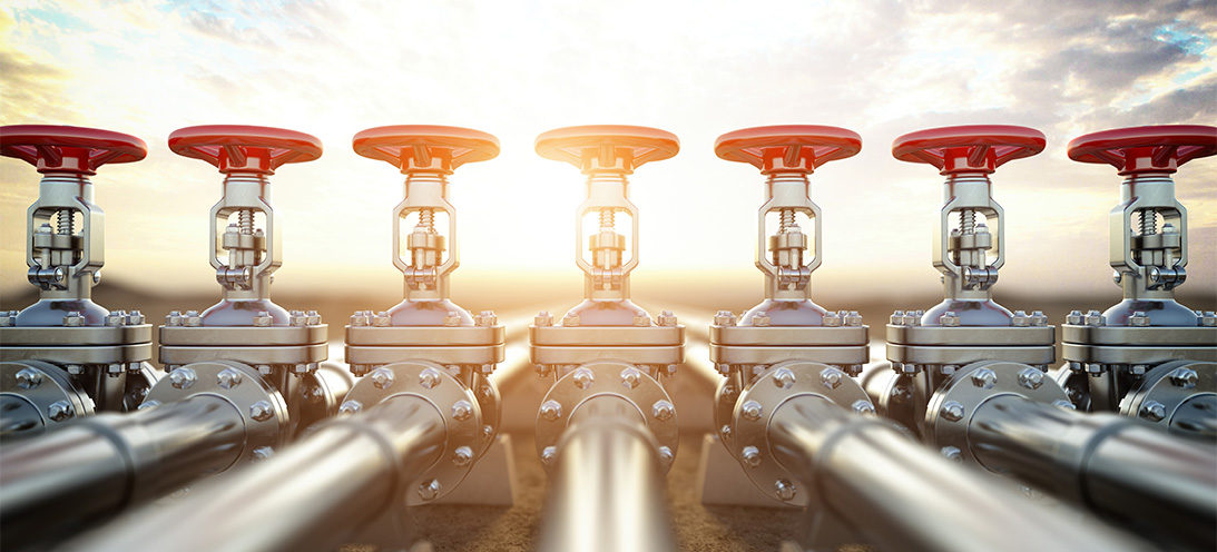
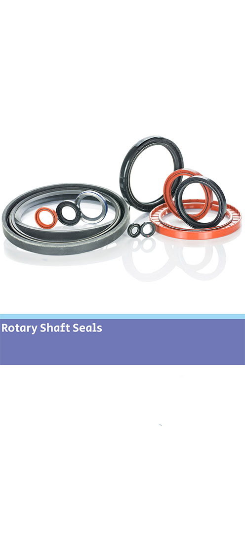
Perfluoroelastomers in valves Seals for valve applicationsSeals for valve applications Valves are imperative for isolation and control functions, and can be found in a broad range of industries such as Oil & Gas, Water & Wastewater, Food & Beverage and Hydraulics & Pneumatics. We supply seal products into valve applications in a variety of styles including ball, gate, flap, plug, butterfly, spool, check and solenoid valves. Characteristics of valve sealing There are many challenges involved in valve application sealing. Conditions and application parameters can vary with temperature extremes from cryogenic up to 325°C, and pressures up to 1000+ bar. Materials need to be carefully considered to suit all fluid compatibility required. Often the seal design requires low breakout friction and offers no stick-slip following prolonged static periods when the valve is not used. Alongside this, customers require long service life and minimal maintenance.Different valve styles include ball, gate, flap, butterfly, spool, check and solenoid valves. Additionally, different types of actuation include manual, pneumatic, hydraulic and electro-mechanical. Different areas of the valve demonstrate different sealing requirements - we explore more below. Valve sealing areas - actuation and body bonnet joint ActuationThere are a range of sealing solutions to suit the variety of actuation types employed with valves. This includes diaphragms for pneumatic actuation, rotary and linear hydraulic and pneumatic seals, and gaskets and O-rings.Seal materials are available to suit all ranges of temperatures and media associated with the actuator and any external contaminants it encounters.Body bonnet jointThis is a static sealing location that can often be sealed with an O-ring (a wide range of materials are available to satisfy fluid compatibility). However, dependent on the fluid, pressures and temperatures, metal seals may be more suited to the application. Additionally, housing deflection under pulsating system pressures may worsen compression set sealing issues. Therefore, a custom gasket design could be potentially more suitable than an O-ring. For subsea valves, a sealing solution capable of handling alternating pressure regimes and multiple media types may be required. Valve sealing areas - stem and seat body StemA critical and dynamic sealing location with often demanding requirements. Depending on the application of the valve, the seals used here may see frequent dynamic operation. They will require a long wear life, whilst in other cases, the valve may be static for long periods. It will then require operation with minimal break-out friction forces; in all cases, reliable sealing is paramount.We manufacture a range of linear and rotary seals for this location, using either elastomer or PTFE options. These include chevron sets, spring energised seals, PTFE slipper seals, wear rings and excluders. Full analysis of the valve duty cycle, internal and external medias and pressures must be considered before the optimum sealing solution can be specified.Seat body Valve seats are often mounted in a housing or carrier which has a sealed interface within the valve body. In these cases it can be a critical location to seal correctly. Dependent on the design, the seal location may be subject to upstream or downstream pressures at various points in the valve operation and in some cases fluid flow through the valve can pull or wash-out seals from their grooves if they are not designed to prevent this. As pressure conditions change with valve operation, the seals here may be required to withstand small (but sometimes frequent) movements of the carrier without sticking or wearing. We have a range of seal types and materials including spring energised PTFE and metal seals that can be used in this location (depending on the exact conditions during valve operation and use). Valve seat A wide variety of elastomers and engineered polymer materials can be moulded or machined to suit valve seat components.Bonded rubber to metal or rubber to plastic seals can provide bespoke solutions that offer benefits in terms of space envelope, component count or ease of assembly. Design & Development for valve sealing applications Our engineering team understand the application demands associated with valve sealing. We will support our customers with the design of seals for every position within the valves.Our service is a complete design process- from initial seal geometry and profile choice, to material selection and prototyping, through to final production. We utilise years of seal design experience and materials expertise. This is alongside technology such as 2D/3D CAD and FEA analysis programs to simulate performance before finalising each individual seal design.We are familiar with the requirements of individual markets and their valve applications, and offer seals manufactured in materials with approval requirements such as NORSOK M-710, ISO23936-2, NACE, WRAS and FDA.For more on our design and engineering service, see our dedicated page HERE
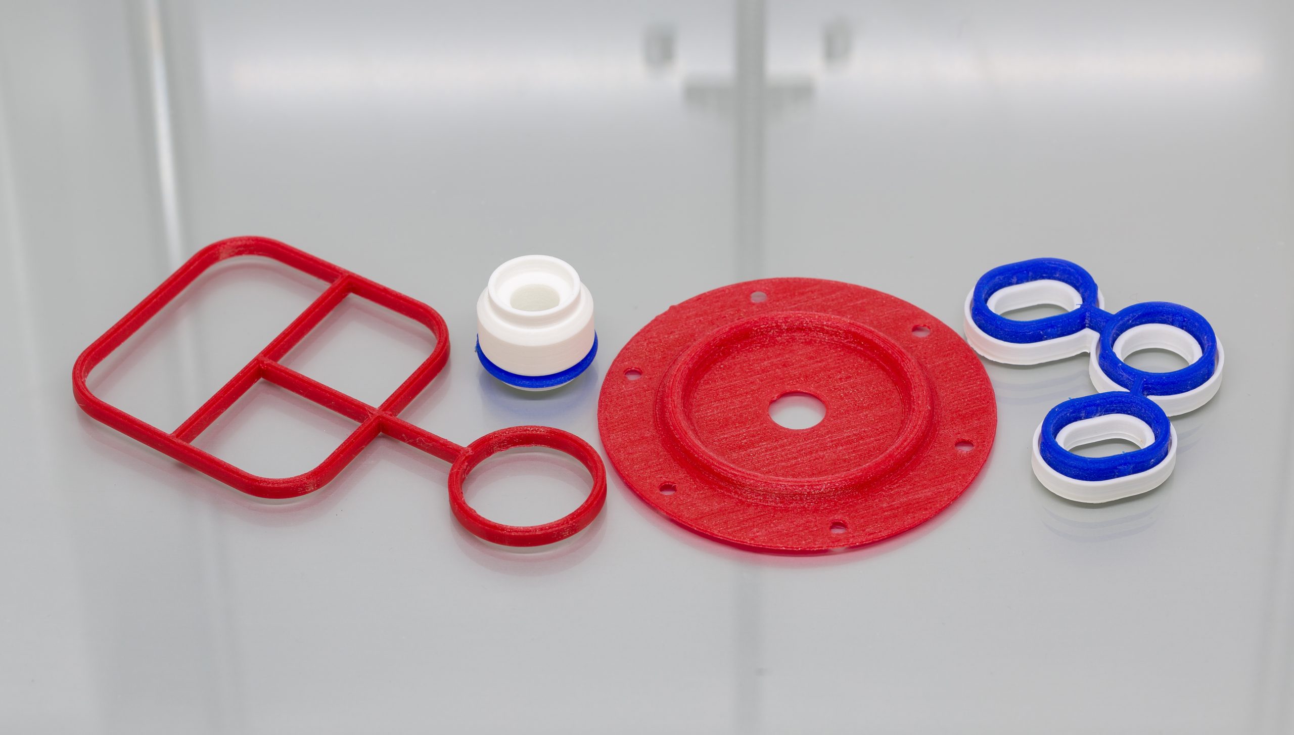
Seals for valve applications 3D printing for seals3D printing for seals 3D printing has developed significantly and now performs a crucial role in many applications. 3D printed products vary from fully functional to purely aesthetic applications – commonly for manufacturing. Here we discuss how our engineers use this technology to demonstrate a seal concept. What is 3D printing? The typically common name for additive manufacturing is 3D printing. The process involves the construction of a three-dimensional shape designed and generated from a computer aided design program (or CAD). The most typical process used for 3D printing is FFF (Fused Filament Fabrication) or FDM (Fused Deposition Modelling).The FDM process uses a continuous filament of a thermoplastic material. It’s then deposited onto the 3D print bed, creating layer by layer, gradually building up the 3D model structure. We commonly use this process to create our design and development range of 3D printed models and seal prototypes. What material is suitable for 3D printing? Material compatibility with the process is imperative and a range of thermoplastic grades are used. Typical suitable material grades include; Polylactic acid (PLA), Acrylonitrile Butadiene Styrene (ABS), Thermoplastic Polyurethane (TPU), Nylon and Polypropylene (PP).The most common grade we use for 3D printing is PLA – for its great strength and stability. We’ve also adapted our design process to use more TPU based material grades, as it loosely demonstrates the same properties as elastomer grades and is better for using in prototype programmes where mechanical fit in groove is tested. Why use 3D printing for seals? 3D printing is used for a variety of designs and seal types. From O-rings, gaskets and lip seals – to grommets, multi shot mouldings and large seal assemblies.Using 3D printing during the initial design stages of a project comes with many benefits. The rapid turnaround means a simple seal design will be produced in around 15 minutes. Additionally, even more complicated parts can be manufactured in the same day. We can even print the application housings – a perfect demonstration to an engineer what they can expect from a seal part. They will see the shape and fit for hardware without the lead time and cost of cutting a prototype tool for moulded parts.This solution is particularly suitable for quick turnaround gasket designs. For example for automotive applications or similar critical markets. Our engineers can design the concept and then 3D print a rapid prototype of a gasket to suit a 3D printed gauge groove. Demonstrating to our customers that the seal has been fit checked for installation, builds further confidence in the design recommendation. Our engineers combine the 3D print with FEA simulation reports to offer a fully engineered sealing solution.Learn more about our design and simulation service HERE
3D printing for seals