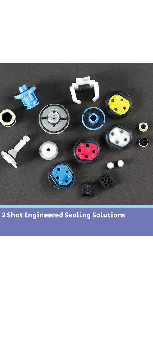
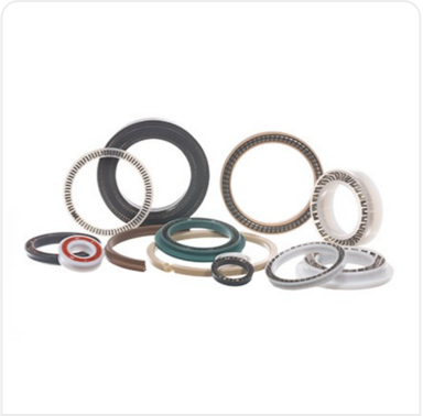
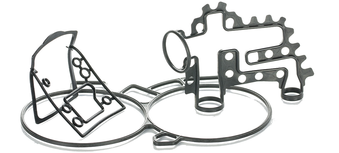
Moulded gaskets for an automotive applicationMoulded gaskets for an automotive application An existing customer (an automotive manufacturer) approached our engineers with an application where they were experiencing failures of a seal designed and manufactured by another rubber seal provider. Here we explore more about our solution for a moulded gasket for this automotive application. The application This gasket is used within a valve housing in an automotive application. The original competitor gasket was experiencing failure at the "T-junction" areas of the seal. Therefore, our customer had experienced chronic failures of their existing design at high temperatures and high pressures.A pulsating pressure of up to 50 Bar and temperatures up to 150°C provide an extreme environment for the seal. Consequently, our engineers reviewed the existing gasket design and application conditions and recommended an increase in height of 0.40 mm.This was to increase the compression and improve the sealing function. Additional beads were also added to further stabilise the gasket in the groove. The challenges We manufactured prototype parts using a single-cavity soft tool and sent them to the customer for in-house testing and validation. The prototype gaskets nearly passed testing but fell just short of the 50 Bar pressure requirement at 150°C, achieving 42 Bar instead. Even so, they significantly improved on the performance of the customer’s original gasket.Upon analysis of customer test data and furthermore by reviewing images of the tested parts, improvements were needed. We determined there were areas where the gasket was sliding in the groove and then shearing as the pressure pulsed. To resolve this issue, our engineers added beads to the rear of the T-intersections of the gasket. This provided additional support, further stabilising the gasket at the high-pressure stress points in the groove. This reduced the amount of movement within the housing.Furthermore, the number of additional beads added needed to be balanced carefully with calculations on groove fill. Further development captured the cleanliness requirements and altered radii on the beads. Customer satisfaction With the new design approved, the customer moved to production tooling stage and sample parts were produced to PPAP Level 3. These parts have since been approved and full production quantities have been ordered manufacturing builds in 2022.For more about our mouldings & gaskets, see our dedicated page HERE.

Moulded gaskets for an automotive application 
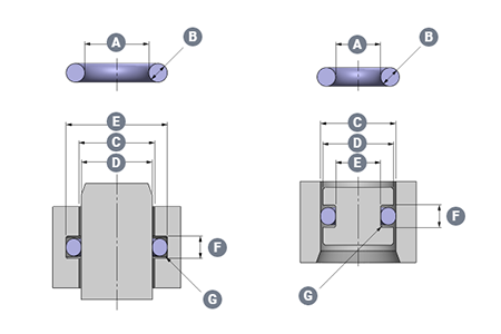
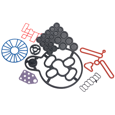
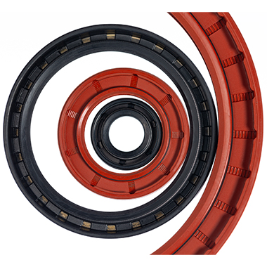
Why use Push-in-Place gaskets?Why use Push-in-Place gaskets? Where a seal groove follows an irregular path or profile, a common sealing solution is to design a custom Push-In-Place (PIP) gasket. This will have the same profile as the centre line of the groove, and simply drops into place, retained by the features of its own design. Gasket sealing overview There are many ways to seal the static join between two components. This could be to keep fluids inside a cavity, or to keep fluids or contaminants out of a device or assembly. The options will vary from simple O-rings, moulded elastomer gaskets and flat sheet style materials, to liquid gaskets (or RTV’s).As with all sealing applications, the optimal sealing solution is designed by first reviewing the application conditions. These include temperature, pressure, fluid exposure etc. Other variables such as life requirement, equipment serviceability and seal compression set will all be considered. Arguably though, compared to other sealing applications there are considerations when designing face, cover or flange sealing solutions. It is imperative to consider the packaging requirements and assembly issues of gasket sealing options. For example, if there is a need to avoid or seal around bolt holes (or other retaining/clamping devices). Additionally, consideration around optimizing hardware wall sections or depths can play an important part in choosing the most suitable gasket sealing technique. What are Push-in-Place gaskets? With the right combination of application conditions, an O-ring style approach to sealing may be the most appropriate. O-rings tend to require relatively shallow grooves compared to their cross section in one half of the assembly. In cases where the groove is round in plan view – they can be a good solution.However, in cases where the groove follows a more irregular path or profile (frequently referred to as a “racetrack”) the O-ring can sometimes pop out in places. This will be often where the two housing parts are being brought together. A common solution is designing a custom moulding with the same profile as the centre line of the racetrack groove. This will simply drop into place.A similar approach is used when the application or hardware constraints steer the design towards a gasket that has a greater cross section depth compared to the width. This would typically be designed so the centre line of the gasket matches the centre line of the groove plan profile – again so that it drops easily into place.An inherent problem with gaskets that can drop into place is that often, they easily drop out of place too. This can occur when the component needs to be inverted or has the potential for rough handling during assembly. Consequently, the gasket may become partially or fully dislodged from the groove, which results in a badly sealed interface. The best solution to this issue is to incorporate retention pips or bumps in the gasket design. This is a solution known as Push-In-Place (PIP) gaskets. These require a distinct force to put them into the groove. Subsequently, they require more than just gravity to get them out of the groove. Why use Push-in-Place gaskets? There are other less effective solutions for tricky groove sealing, such as the use of a sticky grease, or the use of an adhesive. These can bring compatibility and health and safety issues to consider. Additionally, the risk that any contaminant could keep the gasket off the surface that it’s supposed to be sealing against. As a result, the integrity of the seal can be severely compromised.Neither of these approaches can be recommended. Instead, the use of retention pips is a safe and secure way of ensuring the gasket remains in the groove. How do retention pips work on a gasket? To determine the optimum number, size and position of the retention bumps, Finite Element Analysis is used. This ensures they provide sufficient squeeze to prevent the gasket being easily dislodged. Additionally, it’s important the groove space isn’t overfilled with seal material or interfering with the seal compression footprint against the hardware faces.The bumps can be strategically positioned to control any distortion of the gasket under pressure or temperature conditions. For example, low temperature conditions can shrink the gasket and tighten the radius it adopts around a bend in the racetrack profile. This can reduce the seal compression locally and potentially create a leak path.By positioning retention bumps at either end of the bend, the thermal contraction will be controlled to minimize leakage risk.Effective retention is needed to ensure the gasket remains correctly located in the groove even with varied use. For example, if the part needs to be inverted (sometimes the preferred assembly method for practical reasons). Alternatively, it could be subject to rough handling.For large gaskets this is normally the most effective solution. On smaller gaskets (particularly those located well inside the periphery of the assembly), there is a significant risk of a dislodged gasket being totally undetected unless using a PIP gasket design. Monitoring gaskets - human eye or testing machinery It is possible to include tell-tale signs on a gasket design. For example, if a part of the elastomer gasket protrudes sideways through a gap in the housing wall the presence of the gasket can be checked. This will be either with the human eye or an automated vision system. However, this does not ensure correct seating all around the gasket length. Additionally, it cannot be used for internal gasket locations. In these cases a missing or badly fitted gasket would only be discovered during post-build testing, or even worse with a machine failure at a customer.If included at the design stage, the small additional tooling and material costs associated with a PIP gasket are negligible compared to the costs of an impossible assembly scenario, strip and re-build costs on the assembly line, or the consequential costs associated with failure of an assembly once delivered to a customer.More information on PIPs and gaskets can be found HERE
Why use Push-in-Place gaskets?